Roundness and/or dimension measuring device

a measurement device and roundness technology, applied in mechanical measuring arrangements, instruments, manufacturing tools, etc., can solve the problems of high wear level of measuring components in use, and achieve the effects of low resonant frequency, improved measurement accuracy, and finite rigidity

Active Publication Date: 2018-01-30
MOVOMATIC
View PDF19 Cites 7 Cited by
  • Summary
  • Abstract
  • Description
  • Claims
  • Application Information

AI Technical Summary

Benefits of technology

[0018]A particular advantage of the invention is that the measuring accuracy may be additionally improved. Due to the relative change in position between the base body of the measuring device and the workpiece during the orbital motion of the measuring head, caused by motor operation, on the one hand, and external excitation on the other hand, in practice vibrations occur in the measuring system which may become apparent as measurement error or measurement noise. The movable parts of the measuring device may each be regarded as a rigid body in a first approximation. In reality, however, these parts have only finite rigidity, and thus, relatively low resonant frequencies. If the excitation falls in the resonance range of one or more of the components of the movable measuring device, these resonances are excited, resulting in undesirable natural oscillations having a relatively large amplitude, which may become apparent as measurement errors. In this sense, the movable parts of the measuring device should thus be configured to be as rigid as possible, without the weight increase possibly caused which results in higher acceleration values, and thus, higher probing forces (measuring forces). In addition, in practice there are limitations on measures for improving the structural rigidity, since only a limited spatial area is generally available for the measuring device.
[0019]This problem which arises in the measuring device according to the prior art may be addressed at the same time by means of the oscillation damping element provided according to the invention, in that the damper is configured in such a way that it has a relatively low rigidity in the low-frequency range, and has a preferably high rigidity in the high-frequency range. In the high-frequency range, the damper thus represents a mechanical short circuit and acts as a structure-reinforcing element. The natural resonance of the linked measuring rod assembly section is thus increased, so that in many cases the natural resonance is thus no longer excited as strongly, thus reducing the oscillation amplitude.
[0020]The portion of the linkage point of the oscillation damping element on the rod assembly should be selected so that this location is not present in an oscillation node of the natural resonances, in particular not in an oscillation node of the fundamental resonance.
[0021]In addition to the structure-reinforcing and thus resonance-increasing action of the damper, at the same time, a direct damping effect in the form of its ability to convert vibrational energy into heat has a positive impact. In particular for high frequencies, the damping force is set to be approximately constant. The damping effect thus develops primarily at higher (natural) oscillations of the measuring device. This has positive effects on the vibrations, and thus, on the measuring accuracy.
[0022]Thus, due to the oscillation damping element provided according to the invention, it is possible not only to reduce the measuring force, but also to increase the measuring accuracy by avoiding measurement errors caused by oscillations. Another advantage of the measuring device according to the invention is that suitable oscillation damping elements are available as relatively simple, inexpensive standard components, so that the manufacturing costs of a measuring device according to the invention are increased only by a relatively small extent.
[0023]The oscillation damping element may have any suitable design. It is thus possible, for example, to associate a spring-coupled free mass with the measuring device, the free mass being selected to be equal or approximately equal to the (effective) mass of the measuring device, and the coupling spring being dimensioned in such a way that the orbital frequency of the orbital motion of the measuring head results as the resonant frequency. An advantageous further embodiment of the invention provides that the oscillation damping element has a first component and a second component which is linearly movable relative to the first component in an oscillation-damping manner, the first component and the second component in each case being connected via a linkage point to a functional element of the measuring device or a grinding machine provided with the measuring device, and the location of the linkage points being selected in such a way that the distance of the linkage points from one another changes during the orbital rotation of the measuring head. A functional element of the measuring device or of a grinding machine provided with the measuring device is understood to mean any component that is involved in the function of the measuring device or the grinding machine.

Problems solved by technology

One disadvantage of known measuring devices is that a high level of wear of measuring components occurs in use.

Method used


Image

  • Roundness and/or dimension measuring device
  • Roundness and/or dimension measuring device
  • Roundness and/or dimension measuring device

Examples


Embodiment Construction

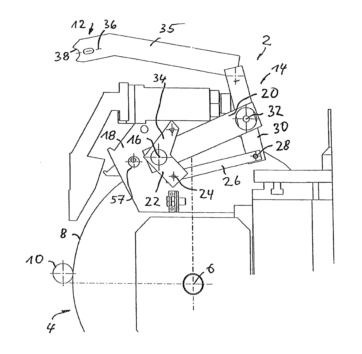
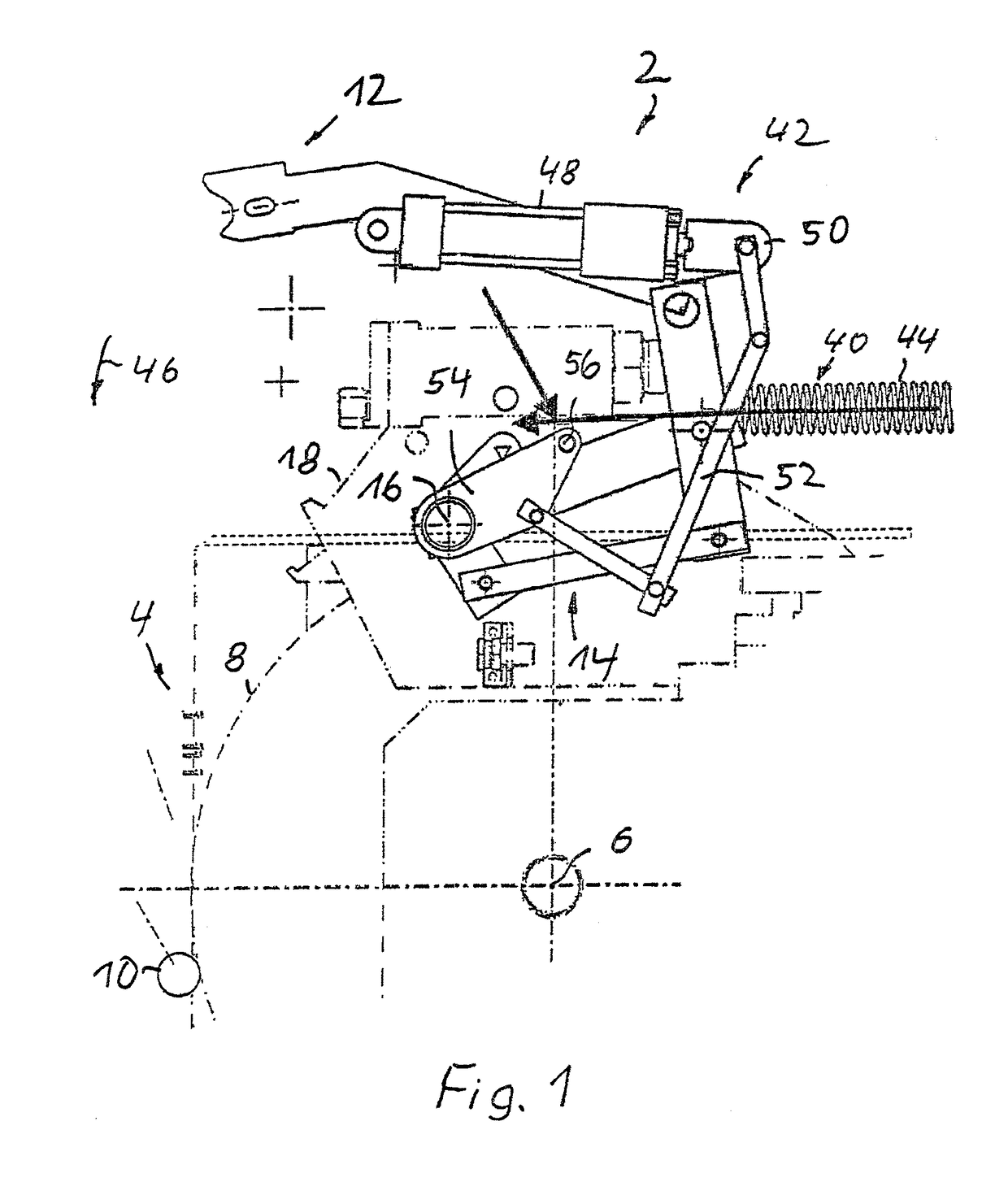
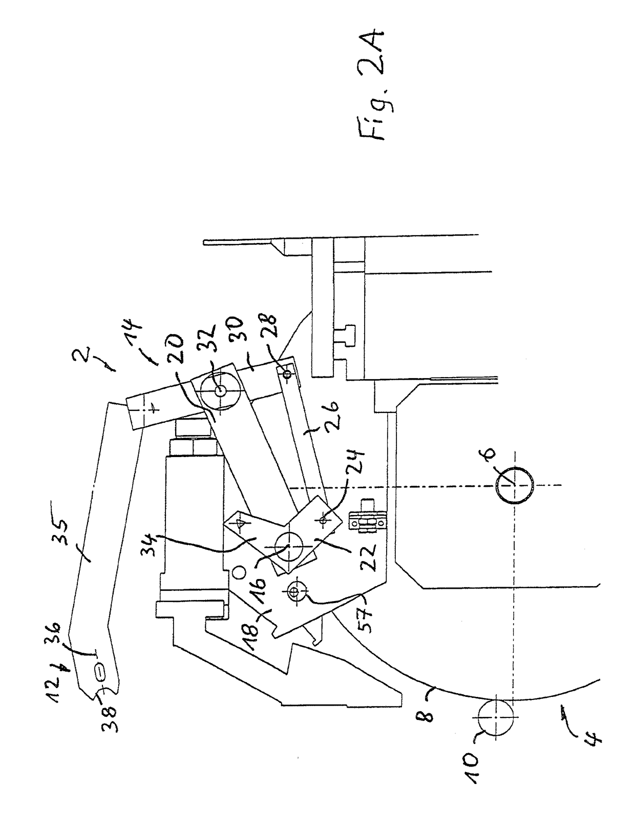
[0046]FIG. 1 shows an illustrative example of a roundness and / or dimension measuring device 2 which is used for in-process measurement of test pieces during a machining operation on a grinding machine 4. The grinding machine 4, which for reasons of simplification is only partially illustrated, has a grinding wheel 8 which is rotatable about a rotational axis 6 fixed to the machine, and which is used for machining a test piece, which in this embodiment is formed by a crank pin 10 of a crankshaft.

[0047]The measuring device 2 has a measuring head 12 which is connected via a rod assembly 14 to a base body 18 of the measuring device 2 so as to be pivotable about a first pivot axis 16.

[0048]The measuring device 2 also has a means, explained in greater detail below, for swiveling the measuring head 12 into a measuring position or swiveling the measuring head out of the measuring position.

[0049]First, the configuration of the rod assembly 14 is explained in greater detail, with reference to...


PUM


Abstract

A roundness and / or dimension measuring device for in-process measurement of crank pins during a machining operation on a grinding machine having a base body, and a measuring head, which is connected to the base body via a rod assembly and which is movable between a neutral position and a measuring position. The measuring head has a measuring probe for contacting the crank pin, and the rod assembly is designed and configured in such a way that the measuring head in the measuring position follows orbital rotations of the crank pin. At least one oscillation damping element is operatively associated with the measuring head for holding it in engagement with the crank pin during the orbital rotation.

Description

CROSS-REFERENCE TO RELATED APPLICATIONS[0001]This application claims priority of German Application No. DE 10 2015 115 718.7, filed 17 Sep. 2015, which is incorporated herein by reference.FIELD OF THE INVENTION[0002]The invention relates to a roundness and / or dimension measuring device for in-process measurement of crank pins during a machining operation on a machining unit, in particular a grinding machine.BACKGROUND OF THE INVENTION[0003]In the manufacture of crankshafts, it is necessary to grind the crank pins of the crankshaft to the proper dimensions on a grinding machine. To ensure that the grinding operation is terminated as soon as a desired dimension is reached, during the machining operation the crank pin must be continually checked, in particular with regard to its diameter and roundness, within the scope of an in-process measurement method.[0004]Roundness and / or dimension measuring devices for in-process measurement of crank pins during a machining operation on a grindin...

Claims


Application Information

Patent Timeline
Patent Type & Authority Patents(United States)
IPC IPC(8): G01B5/20B23Q17/20G01B5/08
CPCG01B5/201G01B5/08B23Q17/20
Inventor VOLK, RAIMUND
Owner MOVOMATIC
Why Eureka
Try Eureka