

Post-implantation contractible or expandable devices and method of using and making the same
- Summary
- Abstract
- Description
- Claims
- Application Information
AI Technical Summary
Benefits of technology
Problems solved by technology
Method used
Image

Examples
Embodiment Construction
[0022]Persons skilled in the art will readily appreciate that various aspects of the present disclosure can be realized by any number of methods and systems configured to perform the intended functions. Stated differently, other methods and systems can be incorporated herein to perform the intended functions. It should also be noted that the accompanying figures referred to herein are not all drawn to scale, but are exaggerated to illustrate various aspects of the present disclosure, and in that regard, the drawing figures should not be construed as limiting.
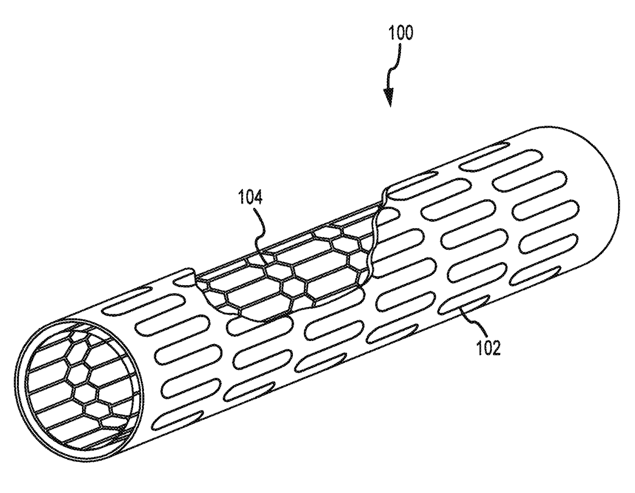
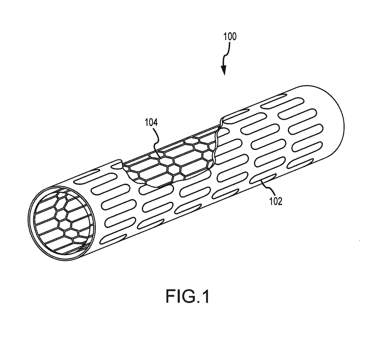
[0023]With that said, and as will be described in more detail herein, various embodiments of the present disclosure generally comprise expandable medical devices having the capability to be over-expanded and to controllably contract back to a neutral state as a support structure bio-corrodes away over time. Various other embodiments of the present disclosure generally comprise a contractible medical device having the capability ...
PUM
| Property | Measurement | Unit |
|---|---|---|
| Fraction | aaaaa | aaaaa |
| Fraction | aaaaa | aaaaa |
| Fraction | aaaaa | aaaaa |
Abstract
Description
Claims
Application Information