Matrix for magnetic separator and magnetic separator

a magnetic separator and matrix technology, applied in the field of matrix and magnetic separator, can solve the problems of poor sorting accuracy, large amount of non-magnetic particles entanglement, poor sorting accuracy, etc., and achieve the effect of enabling previous recognition, high accuracy and high efficiency

Active Publication Date: 2018-02-06
NAT INST OF ADVANCED IND SCI & TECH
View PDF21 Cites 5 Cited by
  • Summary
  • Abstract
  • Description
  • Claims
  • Application Information

AI Technical Summary

Benefits of technology

[0029]According to the present invention, it is possible to overcome the various problems of the conventional techniques and provide a matrix for a magnetic separator and a magnetic separator, the matrix capable of sorting out magnetic particles and non-magnetic particles with high accuracy and high efficiency and enabling previous recognition of a correct magnetic force distribution in a matrix space by simulation.

Problems solved by technology

However, matrices made of an expanded metal, steel wool, etc., in which ferromagnet thin lines constituting the expanded metal, the steel wool, etc. are disposed in an intricately entwined state, have a problem that not only magnetic particles magnetically attractable to the ferromagnet thin lines but also many non-magnetic particles unintended for being magnetically attracted to the ferromagnet thin lines get entangled into the structure of the ferromagnet thin lines, leading to a poor sorting accuracy.
Particularly, at a position at which a locally-high magnetization gradient (ΔB) is generated, magnetic particles magnetically attracted thereto earlier impede passage of non-magnetic particles to come later and block the flow path, leading to a large amount of non-magnetic particles entangled.
Therefore, sparsely disposed ferromagnet thin lines restrict the area effective for magnetically attracting magnetic particles and allow magnetic particles to get through the ferromagnet thin lines via the spaces under the low magnetization gradient (ΔB), leading to the problem of the poor sorting accuracy.
However, matrices made of an expanded metal, steel wool, etc., in which the ferromagnet thin lines are disposed in the matrices in an irregular disposition, have a problem of rejecting previous recognition of a correct magnetic force distribution in the matrix space by simulation or the like.
This entails a problem that an amount processable by one detaching / recovering operation is low, leading to a poor sorting efficiency.
Further, because of the incapability of previously recognizing a correct magnetic force distribution in the matrix space by simulation or the like, it is unknown until a matrix is actually prototyped and used for a sorting test whether the matrix has a good performance or not, which has disturbed development of a high-performance matrix.

Method used


Image

  • Matrix for magnetic separator and magnetic separator
  • Matrix for magnetic separator and magnetic separator
  • Matrix for magnetic separator and magnetic separator

Examples


examples

Simulation of Magnetic Force Distribution

[0080]A magnetic force distribution in a matrix in a case where the matrix for a magnetic separator of the present invention is employed as a matrix for a magnetic separator used in a magnetic separator was simulated with analyzing software (FEMM 4.2, free software created by David Meeker).

[0081]FIG. 3 illustrates the configuration of the matrix (wavelike matrix) for a magnetic separator for which the simulation was conducted, and a result of a finite element method-based simulation of a magnetic force (BΔB) distribution for the wavelike matrix (a magnetic force distribution in the matrix space) under a condition that a density of a magnetic flux generated by an electromagnet formed of an air core coil (hereinafter, referred to as air core magnetic flux density) was 1 T.

[0082]As illustrated in FIG. 3, a wavelike matrix 10 includes a plurality of entirely approximately wavelike plate-shaped magnetic walls 11 in each of which wave-shaped bent s...

example

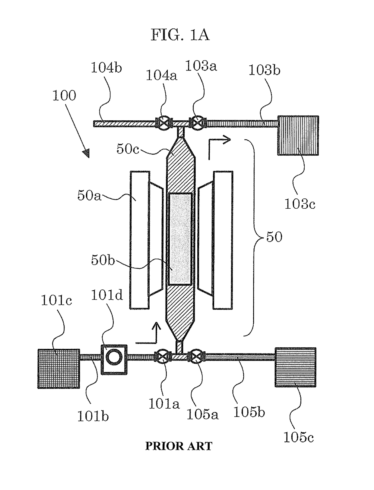
[0122]A magnetic separator according to Example was produced by employing the wavelike matrix 10 (see FIG. 3) having a wave height h of 300 μm and an inter-vertex pitch p of 4 mm as a matrix 50b for a magnetic separator in the magnetic separator 100 illustrated in FIG. 1A. A sorting test was performed with this magnetic separator in the manner described below.

[0123]The sorting target slurry used was a slurry having a solid concentration of 10% that was obtained by mixing two kinds of solid particles presented in Table 2 below (a sample A with a high magnetic susceptibility; a green phosphor LAP and a sample B with a low magnetic susceptibility; a red phosphor YOX) in pure water in which a dispersant NOPCOSANT RFA available from San Nopco Ltd. (0.15% by mass) and a dispersant SN WET 980 available from San Nopco Ltd. (0.015% by mass) were added. In a state that the electromagnet was excited, the sorting target slurry was introduced into the magnetic separation flow path through the so...


PUM


Abstract

To provide matrix for magnetic separator capable of sorting magnetic and non-magnetic particles highly accurately and efficiently and enabling previous simulative recognition of correct magnetic force distribution in matrix space, and magnetic separator.Matrix for magnetic separator of present invention includes: entirely approximately wavelike plate-shaped magnetic walls each having orderly structure of wave-shaped bent sections continuously repeatedly formed in wave advancing direction and each having wave height h of ≦1 mm and approximately inverted V- or U-shape; and entirely approximately box-shaped housing part housing magnetic walls and having in opposite surfaces, introducing and discharging parts through which sorting target fluid containing magnetically-attractable substance magnetically-attractable to magnetic walls is passed thereinto / therefrom, magnetic walls arranged in juxtaposition such that convex shapes of wave-shaped bent sections in one magnetic wall face concave shapes thereof in another magnetic wall adjacent to one magnetic wall with constant interval therebetween.

Description

TECHNICAL FIELD[0001]The present invention relates to a matrix for a magnetic separator based on a magnetic separation method, and to a magnetic separator including the matrix for a magnetic separator.BACKGROUND ART[0002]A magnetic force of attracting a magnetic particle to a magnet is represented by a product between a magnetic flux density (B) and a magnetization gradient (AB) at a position at which the magnetic particle is placed. A magnetic separation method of placing thin lines of a ferromagnet under a uniform magnetic field and generating a high magnetization gradient near the thin lines was proposed in the late 1960s and then evolved to high gradient magnetic separators in the United States. Nowadays, magnetic separators utilizing similar principles are sold by many magnetic separator manufacturers.[0003]For example, a Jones-type wet high gradient magnetic separator is widely used as the magnetic separator. FIGS. 1A and 1B are depictive diagrams depicting overviews of a Jone...

Claims


Application Information

Patent Timeline
Patent Type & Authority Patents(United States)
IPC IPC(8): B03C1/032B03C1/02B03C1/033B03C1/034B03C1/28
CPCB03C1/02B03C1/032B03C1/288B03C1/0335B03C1/034
Inventor OKI, TATSUYAHAZUMI, TAEKONOGUCHI, TOMOHIRO
Owner NAT INST OF ADVANCED IND SCI & TECH
Why Eureka
Try Eureka