Aero engine rotor air floatation assembling device based on gantry structure

a technology of gantry structure and rotor, which is applied in the direction of machines/engines, mechanical equipment, instruments, etc., can solve the problems of poor coaxality after the rotor assembly, no guidance for assembling the aero engine rotor, and inability to improve the influence of geometric quantity on the assembling, so as to save 40% mounting time and cost, improve engine stability, and reduce engine vibration

Inactive Publication Date: 2018-02-13
HARBIN INST OF TECH
View PDF19 Cites 2 Cited by
  • Summary
  • Abstract
  • Description
  • Claims
  • Application Information

AI Technical Summary

Benefits of technology

[0011]Aiming at the disadvantages existing in the prior art above, an aero engine rotor air floatation assembling method and device based on a gantry structure are proposed to solve the problem of low coaxality after the aero engine rotor is assembled, so as to achieve the aims of high coaxality after the rotor is assembled, reduced vibration, mounting easiness, high flexibility and improved engine performance.
[0017]The present invention can obtain the coaxality weight of each rotor by measuring the concentricity and verticality of each rotor, and then can obtain the guidance mounting angle by vector optimizing the coaxality weight of each rotor, therefore, can save 40% mounting time and cost, obtain 98% one-time mounting success rate, predict the mounting progress, improve engine stability, reduce engine vibration, save engine fuel consumption, reduce CO2 emission, and reduce engine noise pollution.

Problems solved by technology

However, in real production, the assembling of the aero engine is completely hand-assembled, and the accuracy degree and the stability of the assembling depends entirely on the operational experience and technical level of the assembling workers, therefore, there is a lack of a fast and efficient method that guides the assembling of the aero engine rotor, improves the assembling efficiency, reduces the vibration of the aero engine and improves the performance of the aero engine.
This method has the following problem: the influence of the aspect of the geometric quantity of the rotor on the assembling is not analyzed, therefore, it is impossible to improve the influence of the geometric quantity on the assembling.
This method has the following problem: there is no guidance for assembling the aero engine rotor.
This method has the following problem: only the coaxality of the measured part is measured, and the problem of poor coaxality after the rotor is assembled is not solved.
This method has the following problem: the influence of the axial mounting plane during the assembling the rotor to the assembled rotor is not considered.
The high-speed rotation speed of the high-performance engine is larger than 10000 rpm when it is working, and the axial or radial deflection of the single component will inevitably result in that the center of the turbine disk offsets from the rotation axis of the engine, therefore, a very large centrifugal force will be generated under such condition, which will lead to unbalance of the rotor rotation and lead to engine vibration, thereby ensuring that the coaxality after each component is assembled is the important and difficult issue to be solved during mounting.
As for a model assembling without using coaxality optimization method, due to processing precision limitations, there are errors in the axial direction and radial direction of each component, such as jitter, eccentricity, inclination and so on.
If it is assembled directly and randomly, so it may have the case that a bending similar to the “banana” is formed, that is, the eccentricity and inclination errors of each lower component are accumulated to the upper component, resulting in entire deflection and great inclination after the assembling, and leading to poor coaxality of the engine rotor, and therefore, it is difficult to satisfy application requirements
This method is time consuming, and the possibility to rework is large, which affects the mounting efficiency and the one-time success rate, and usually, the one-time successful assembling needs 4-5 days.
Moreover, since the position is not the optimal assembling position, it usually requires dismounting 4-5 times and also requires the workers to assemble with rich experience, and each assembling needs to go through hot working and cold working.
Thus, the current aero engine assembling method has low mounting efficiency, and it is difficult to mount.
Besides, the coaxality is poor after assembling, which affects engine performance.

Method used


Image

  • Aero engine rotor air floatation assembling device based on gantry structure
  • Aero engine rotor air floatation assembling device based on gantry structure

Examples


Embodiment Construction

[0047]Hereinafter, the present invention will be described in further detail with reference to the drawings:

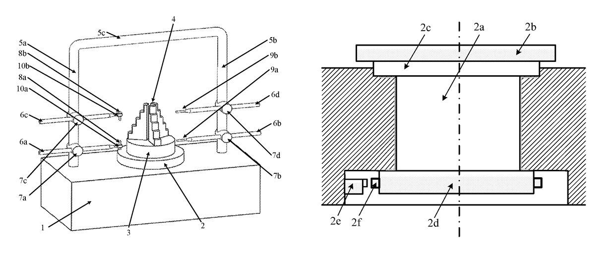
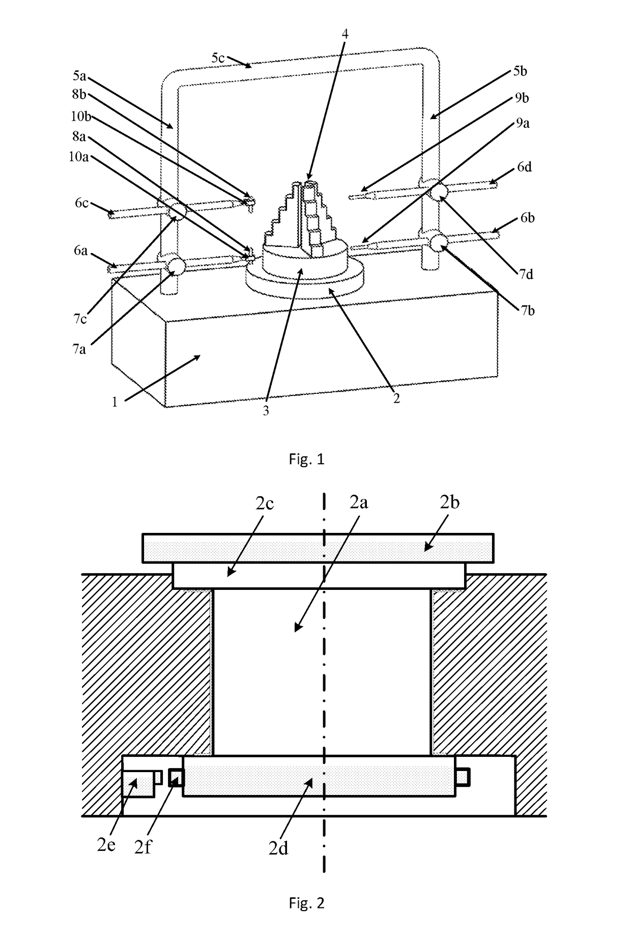
[0048]An aero engine rotor air floatation assembling method and device based on a gantry structure are provided, and the method and device are: a three jaw electric chuck 4 is disposed on the central position of a worktable for adjusting concentricity and inclination 3. A door shaped left pillar 5a and a door shaped right pillar 5b are symmetrically distributed on the both sides of an air bearing 2 and are fixedly mounted on the base 1, and the both ends of a door shaped lateral beam 5c are fixedly connected with the upper end of the door shaped left pillar 5a and the upper end of the door shaped right pillar 5b. A left upper pillar-rod connector 7c and a left lower pillar-rod connector 7a are movably adjustably sleeved on the door shaped left pillar 5a sequentially from top to bottom, and a left upper lateral measuring rod 6c is horizontally nested on the left upper pillar-ro...


PUM


Abstract

An aero engine rotor air floatation assembling method and device based on a gantry structure belong to mechanical assembling technology. The present invention can effectively solve the problem of poor coaxality after the aero engine rotor is assembled and has the characteristics of high coaxality after the rotor is assembled, reduced vibration, mounting easiness, high flexibility and improved engine performance. The measuring method and device are: determining rotary reference based on a rotary air bearing; determining the angular positioning of a rotary table according to a grating ruler; extracting the radial error of the radial mounting plane and the inclination error of the axial mounting plane of the rotor based on the four-probe measuring device to obtain the influencing weight of this rotor to the assembled rotor on coaxality; measuring respectively all the rotors required for assembling to obtain the influencing weight of each rotor to the assembled rotor on coaxality; vector optimizing the weight of each rotor to obtain the assembling angle of each rotor.

Description

[0001]This application is the U.S. national phase of International Application No. PCT / CN2014 / 095057 filed 26 Dec. 2014, which designated the U.S. and claims priority to CN Patent Application No. 201410052282.X filed 14 Feb. 2014, the entire contents of each of which are hereby incorporated by reference.TECHNICAL FIELD[0002]The present invention belongs to mechanical assembling technology, and mainly relates to an aero engine rotor air floatation assembling method and device based on a gantry structure.BACKGROUND ART[0003]Aero engine assembling is the last sector in the manufacturing process of an aero engine, and is also one of the most important manufacturing sectors. Under existing aero engine design and processing technology conditions, the quality and the working efficiency of the assembling make great contributions to the quality, performance and working efficiency of the engine. Therefore, during the assembling, the coaxality of the rotor after being mounted should be increas...

Claims


Application Information

Patent Timeline
Patent Type & Authority Patents(United States)
IPC IPC(8): F01D25/28G01B7/31G01C9/06
CPCF01D25/28G01B7/31G01C2009/064G01C9/06F05D2230/60F01D5/027F01D25/285F05D2260/83
Inventor TAN, JIUBINSUN, CHUANZHIWANG, LEIZHAO, BO
Owner HARBIN INST OF TECH
Why Eureka
Try Eureka