
Method of operating an exhaust gas aftertreatment

a technology of exhaust gas and aftertreatment, which is applied in the direction of exhaust treatment, electrical control, instruments, etc., can solve the problems of reducing the efficiency of exhaust gas treatment, so as to reduce the amount of exhaust gas, reduce the effect of exhaust gas consumption

Active Publication Date: 2018-02-13
ROLLS ROYCE SOLUTIONS GMBH
View PDF17 Cites 0 Cited by
  • Summary
  • Abstract
  • Description
  • Claims
  • Application Information

AI Technical Summary

Benefits of technology

The invention is about a method for checking the status of a diesel particulate filter and regulating its exhaust gas temperature to reduce emissions. The method includes measuring the pressure difference between two points in the exhaust system and comparing it to a threshold value to initiate a regeneration step when necessary. This allows for a more efficient use of engine power and reduces unnecessary consumption. Additionally, the measured pressure values are filtered to eliminate outliers and improve accuracy.

Problems solved by technology

The above-mentioned computational methods are comparatively complicated.
It has been found, however, that the cause of the differential pressure is comparatively complex.
Whereas soot comprises essentially combustible carbon components, ash is defined as the incombustible component of a filter load, which is almost impossible to remove during operation or which at best requires considerable effort to do so.
During operation, however, the increase in the differential pressure caused by the ash load leads in particular to the situation that, either a reference value pertaining to the differential pressure for initiating regeneration is reached at an increasingly earlier point, or a reference value calculated on the basis of the combustion ends up being too low.

Method used


Image

  • Method of operating an exhaust gas aftertreatment
  • Method of operating an exhaust gas aftertreatment
  • Method of operating an exhaust gas aftertreatment

Examples


Embodiment Construction

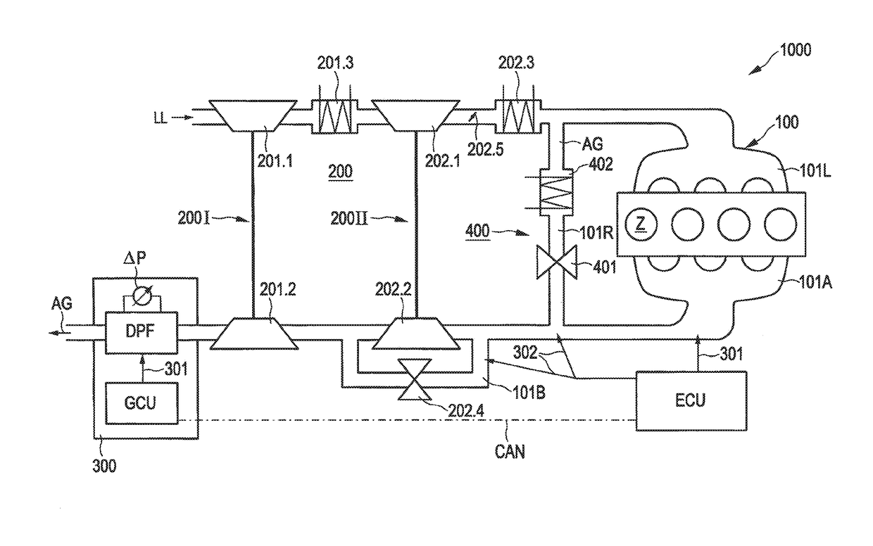
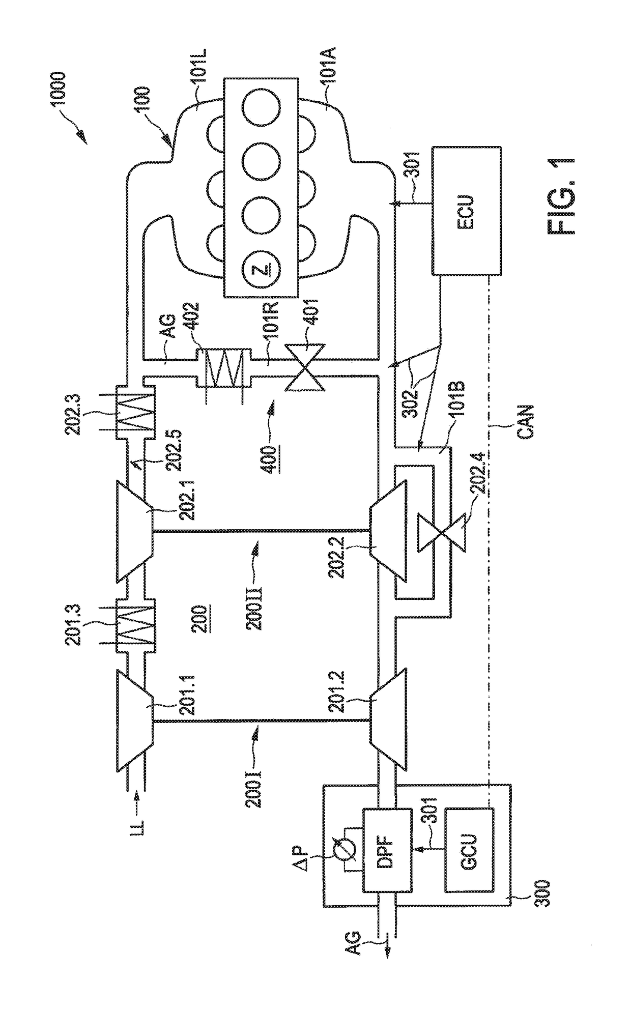
[0053]FIG. 1 shows an internal combustion engine 1000 with an engine 100, a charger 200, and a symbolically indicated exhaust gas aftertreatment system 300 comprising a diesel particulate filter DPF, which can be subjected to thermomanagement measures by means of a control unit GCU for the passive regeneration of the diesel particulate filter DPF. In the present case, the control unit GCU of the exhaust gas aftertreatment is accommodated as a module in a system comprising the exhaust gas aftertreatment system, the diesel particulate filter, and the control unit GCU. In the present case, the control unit for controlling the passive regeneration of the diesel particulate filter—symbolized by the arrow 301—is functionally connected to a central control unit ECU of the internal combustion engine 1000 by a data and control bus CAN. The central control unit ECU, furthermore, as symbolically indicated by the arrows 301, 302 is configured to control the engine 100 and the charger. In the pr...


PUM

PropertyMeasurementUnit
volumetric flow rateaaaaaaaaaa
differential pressureaaaaaaaaaa
exhaust gas temperatureaaaaaaaaaa

Abstract

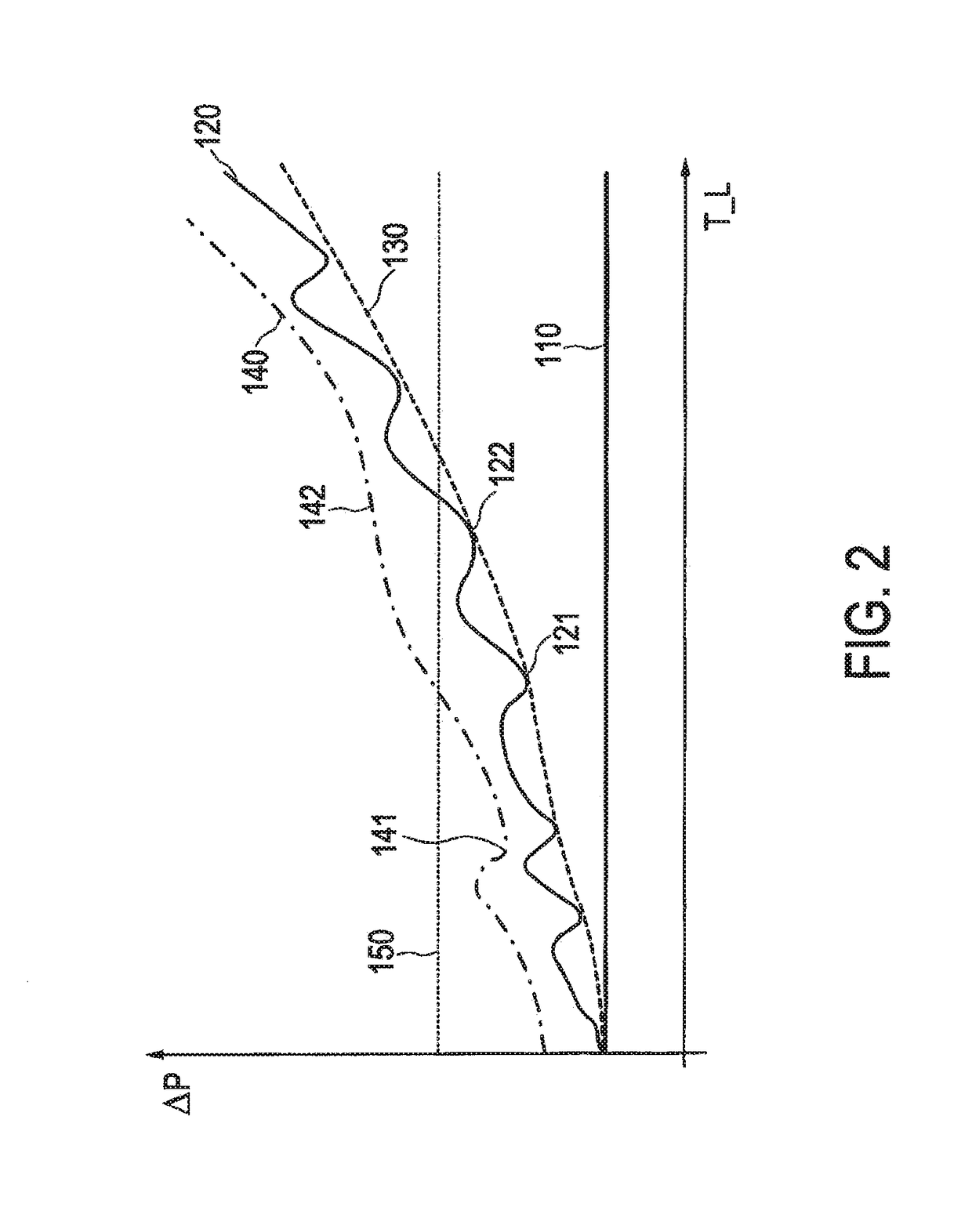
A method and a device for operating an exhaust gas aftertreatment, wherein a diesel particulate filter is regenerated during the operation, in particular passively regenerated, wherein a corrected differential pressure is calculated from a current differential pressure across the diesel particulate filter at a current exhaust gas volumetric flow rate and with a current correction factor. The current correction factor is determined by determining a lower differential pressure in a predetermined time interval at a defined exhaust gas volumetric flow rate, in particular in a specified exhaust gas volumetric flow rate interval around the defined exhaust gas volumetric flow rate, and comparing the lower differential pressure with a specified current reference value and, depending thereon, calculating a new correction factor or retaining the previous correction factor as the current correction factor.

Description

[0001]The present application is a 371 of International application PCT / EP2014 / 001489, filed Jun. 3, 2014, which claims priority of DE 10 2013 210 898.2, filed Jun. 11, 2013, the priority of these applications is hereby claimed and these applications are incorporated herein by reference.BACKGROUND OF THE INVENTION[0002]The invention pertains to a method for operating an exhaust gas aftertreatment with a diesel particulate filter and a device for controlling the exhaust gas aftertreatment. The invention also pertains to an exhaust gas aftertreatment and to an internal combustion engine.[0003]It is known from the prior art that diesel particulate filters can be used to remove soot particles from an exhaust gas. Diesel particulate filters can comprise a fine-pored structure—e.g., a ceramic structure or, as described in US 2007-151,231 A, a fine-pored woven steel structure—on the walls of which the soot particles are deposited. It is known that diesel particulate filters can be regenera...

Claims


Application Information

Patent Timeline
Patent Type & Authority Patents(United States)
IPC IPC(8): F01N3/00F01N9/00G01L27/00F01N11/00F01N3/02F02D41/24F02D41/02F02D41/14F01N3/023
CPCF01N9/002F01N11/00F02D41/029F02D41/1448F02D41/2429G01L27/002F01N3/023Y02T10/47F01N3/0231F01N2550/04F01N2560/08F01N2900/1406F01N2900/1411F01N2900/1611F02D2200/0812Y02T10/40
Inventor PROSPERO, ANDREASPADER, TIMMERK, STEFAN
Owner ROLLS ROYCE SOLUTIONS GMBH
Learn More