Fault detection system for actuator

a fault detection and actuator technology, applied in the field of fault detection systems, can solve the problems of increasing the cost of the system, time-consuming, and high cost of the fault detection system, and achieve the effects of reducing the number of processing steps required for maintenance, enhancing the maintainability of equipment including the actuator, and reducing the burden on the operator

Active Publication Date: 2018-02-13
SMC CORP
View PDF10 Cites 7 Cited by
  • Summary
  • Abstract
  • Description
  • Claims
  • Application Information

AI Technical Summary

Benefits of technology

[0024]The present invention seeks to resolve the aforementioned problems, and has the object of providing a fault detection system for an actuator, in which maintainability of the fault detection system can be enhanced, by easily detecting faults of the actuator without requiring stoppage of the equipment.
[0058]In accordance with the ninth feature, by visually confirming the content displayed on the display device, the operator can grasp the occurrence of a fault of the actuator, and can quickly carry out an appropriate action such as halting operation of the equipment, replacing the actuator, etc.

Problems solved by technology

For this reason, in the event that a fault of a small sized actuator 106 which operates at high speed is to be detected, it is necessary to construct a measurement system including a controller 132 having a high processing speed, thus increasing the cost of the system.
Additionally, in the case that plural actuators are used in one set of equipment, the user must create controller programs for measuring the stroke times of all of the actuators, and set such programs in the PLC, which is time consuming.
Further, since a large capacity memory and a PLC with advanced programming capabilities are needed for storing the controller programs and the measurement results, construction of the fault detection system 130 tends to be expensive.
Moreover, in the techniques disclosed in Patent Document 1 and Patent Document 2, similar problems to those of the fault detection system 130 of FIG. 10 are raised.

Method used


Image

  • Fault detection system for actuator
  • Fault detection system for actuator
  • Fault detection system for actuator

Examples


Embodiment Construction

[0070]A preferred embodiment of a fault detection system for an actuator according to the present invention will be described in detail below with reference to the accompanying drawings.

[Overall Configuration of Fault Detection System]

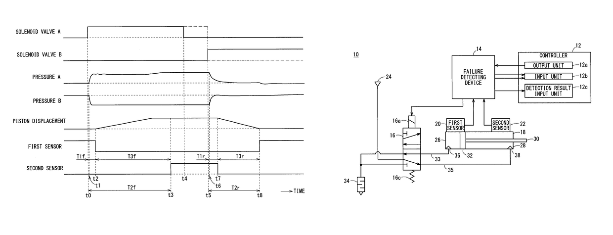
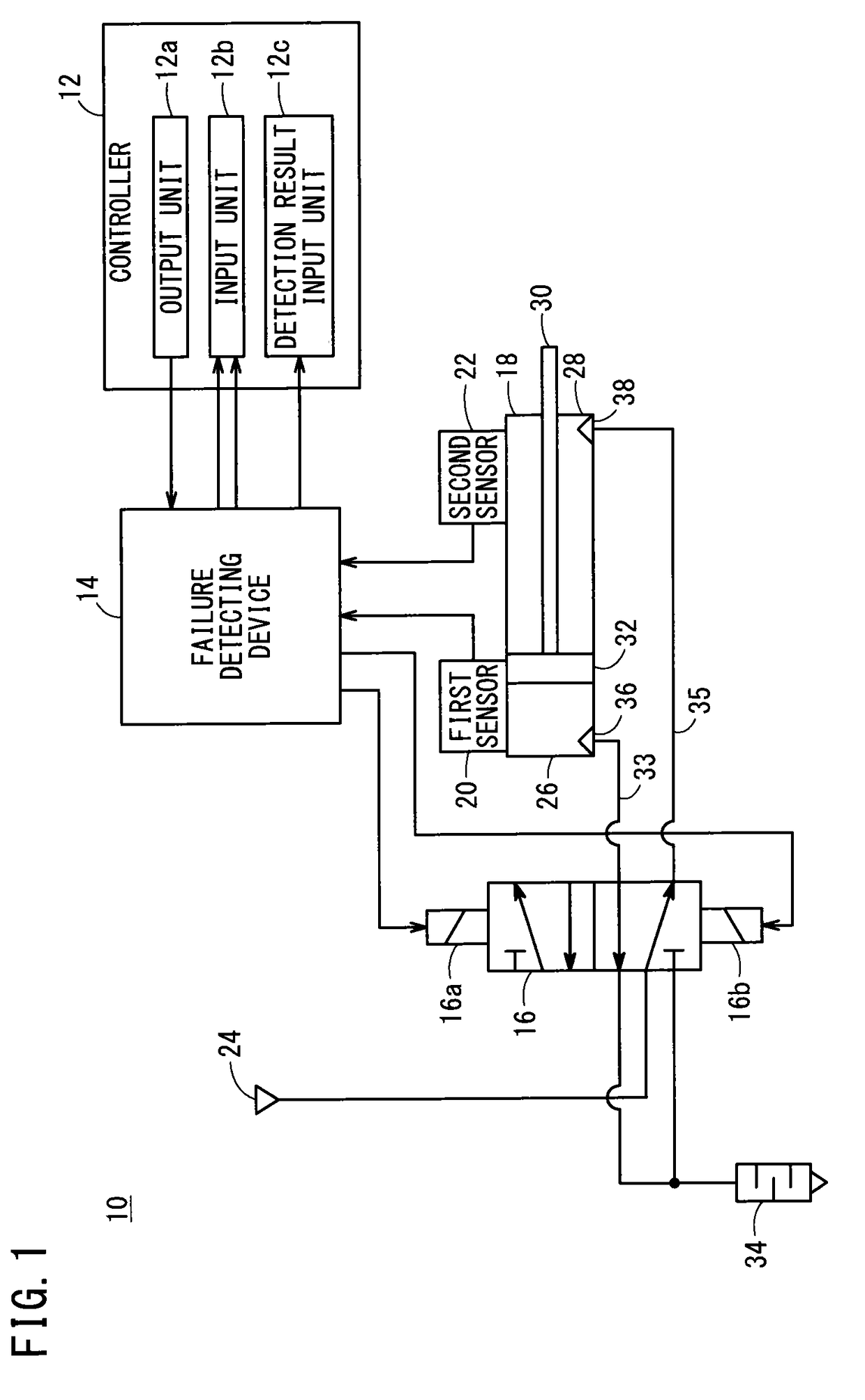
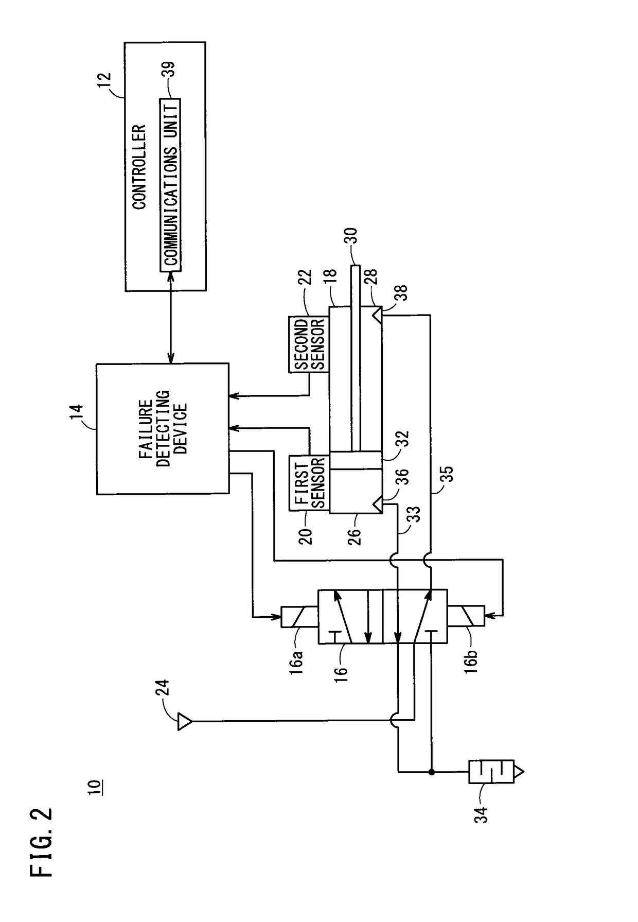
[0071]As shown in FIG. 1, a fault detection system 10 for an actuator according to the present embodiment (hereinafter referred to as a fault detection system 10 according to the present embodiment) is equipped with a controller 12 such as a PLC or the like, a failure detecting device 14 (fault detecting device), a directional switching valve 16 comprising a 4-way, 5-port double-acting solenoid valve, an actuator 18 such as a fluid pressure cylinder or the like, and a first sensor 20 (first sensor) and a second sensor 22 (second sensor), which are arranged on an outer circumferential surface of the actuator 18.

[0072]The fault detection system 10 is incorporated in non-illustrated equipment to make up a system that is equipped with a failure prediction ...


PUM


Abstract

A failure detecting device of a fault detection system includes a detection time calculator, which calculates a stroke time T3 required for a piston to travel between one end and another end of an actuator based on detection signals from a first sensor and a second sensor, a statistical processor that performs a predetermined statistical calculation with respect to the stroke time T3, and a fault response detector, which detects whether or not a fault of the actuator has occurred based on a processing result of the statistical processor.

Description

CROSS-REFERENCE TO RELATED APPLICATION[0001]This application is based upon and claims the benefit of priority from Japanese Patent Application No. 2013-142556 filed on Jul. 8, 2013, the contents of which are incorporated herein by reference.BACKGROUND OF THE INVENTION[0002]Field of the Invention[0003]The present invention relates to a fault detection system for detecting an abnormality of an actuator, based on a movement time of a movable member in the actuator.[0004]Description of the Related Art[0005]With an actuator in which a movable member is displaced upon supply of a pressure fluid (e.g., a pressurized gas), maintenance typically is carried out prior to the occurrence of a fault, when the frequency of use or a number of operations (operating time, duration of use) thereof reaches a given empirically determined level.[0006]However, conventionally, even with a normal actuator that is not currently suffering from deterioration, under routine maintenance, replacement of the actua...

Claims


Application Information

Patent Timeline
Patent Type & Authority Patents(United States)
IPC IPC(8): F15B19/00F15B15/28G01M13/00
CPCG01M13/00F15B15/2815F15B19/005F15B2211/864F15B2211/7653F15B2211/857F15B2211/6336B25D9/26B41J2/0451F15B15/24F01L9/16
Inventor AKI, TOMOHIKO
Owner SMC CORP
Why Eureka
Try Eureka