Wave power generation device and method for operating and maintaining the same

a power generation device and wave technology, applied in the direction of machines/engines, servomotors, vessel construction, etc., can solve the problems of high maintenance costs, poor wave/wind resistance of the device, complex assembly process of the device, etc., to achieve simple and novel structure, convenient operation, and high reliability

Active Publication Date: 2018-02-27
DALIAN UNIV OF TECH +1
View PDF21 Cites 6 Cited by
  • Summary
  • Abstract
  • Description
  • Claims
  • Application Information

AI Technical Summary

Benefits of technology

[0006]In view of the above-described problems, it is one objective of the invention to provide a wave power generation device comprising floating towers and a floating platform. The wave power generation device is safe, reliable, economical, and multifunctional, and features simple and novel structure, convenient operation, strong resistance to wind and wave, and high generation efficiency.
[0015]1) transporting the floating platform to a work place; loading ballast water to a ballast tank to allow the floating platform to sink, so that the swing plate reaches an operating depth, and the floating platform stays in an appropriate floating state; anchoring the gravity anchors to four corners so that the floating platform faces a wave transmission direction; adjusting lengths of the anchor chains via the anchor windlasses and changing pre-tensioning forces of the anchor chains to buffer a motion response of the floating platform caused by a combined effect of wind, current, and waves;
[0019]The wave power generation device is an assembled structure comprising the floating platform, the floating towers, the connecting member, the power generation assembly, the control unit, the anti-sway plates, and the mooring system. The floating platform is the carrier of the power generation assembly. The symmetrically arranged floating towers provide buoyance force and stability for the wave power generation device. The floating platform and the floating towers are connected via the lightweight connecting member. The wave power generation device features a simple and novel structure. Whilst meeting the requirements for functions, the wave power generation device decreases the weight of the structure, saves the production cost, reduces the adverse impact of the components of the wave power generation device on the wave motion, improves the penetrability of the wave motion, and increases the efficiency of the wave energy collection. The floating towers comprise the ballast tank, the pump room, and the control unit in the control cabin, which is favorable to the adjustment of the floating state of the wave power generation device, thus ensuring the swing plate is in an optimal operating depth, and satisfying the requirements for the maintenance and towing of the wave power generation device.
[0020]The anti-sway plate is disposed on the outer side of the floating towers, which reduces the swing of the wave power generation device. The connecting member is connected to the floating towers and the floating platform, and the joints thereof are provided with diagonal bracings, which guarantees the intensity and security of the wave power generation device. The radial mooring system is economical, reliable and easy to operate, and increases the wind / current / wave resistance of the wave power generation device. The wave power generation device is safe, reliable, economical and multifunctional, and features simple and novel structure, convenient operation, and high generation efficiency.

Problems solved by technology

Conventional wave power generation devices have the following disadvantages: 1. the assembly process of the devices is complex; 2. the maintenance costs are high; 3. the wave / wind resistance of the devices is poor; and 4. the floating platform of the wave power generation devices tends to impede the wave energy transmission.

Method used


Image

  • Wave power generation device and method for operating and maintaining the same
  • Wave power generation device and method for operating and maintaining the same
  • Wave power generation device and method for operating and maintaining the same

Examples


Embodiment Construction

[0033]For further illustrating the invention, experiments detailing a wave power generation device comprising floating towers and a floating platform and a method for operating and maintaining the same for wave energy collection and conversion are described below. It should be noted that the following examples are intended to describe and not to limit the invention.

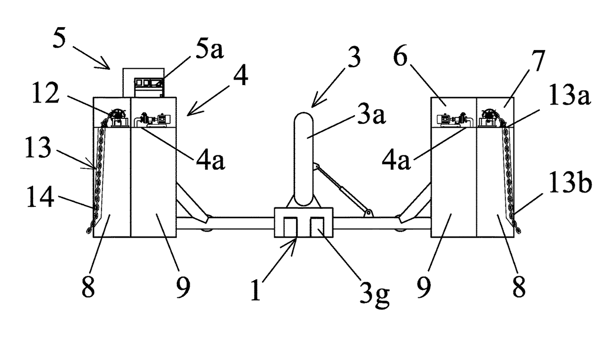
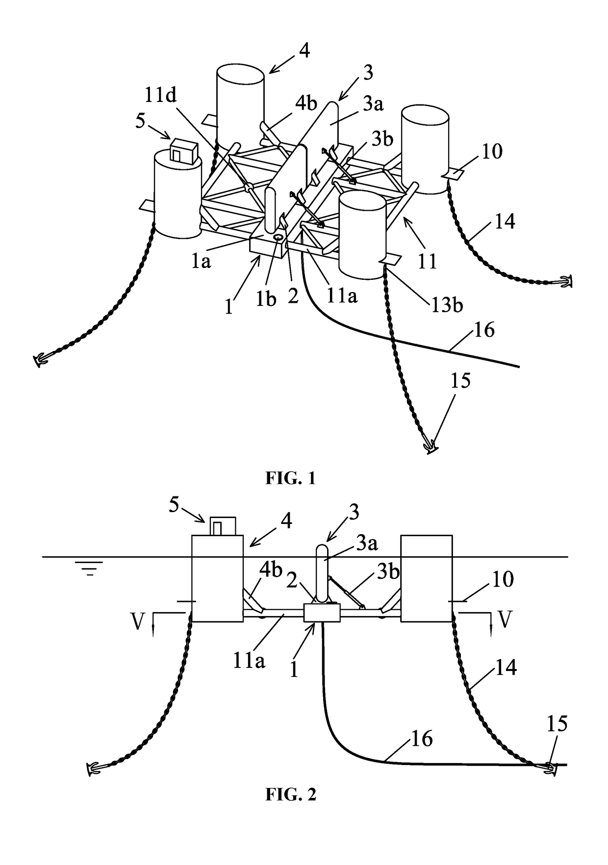
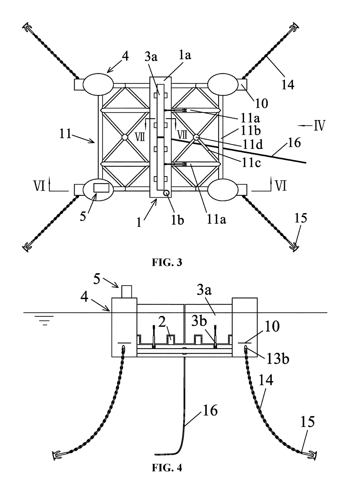
[0034]FIGS. 1-4 are schematic diagrams of a wave power generation device having a connecting member in a truss structure. The wave power generation device comprises a floating platform 1, floating towers 4, a connecting member 11, a power generation assembly 3, a control unit 5a, a mooring system, and an anti-sway device. The floating platform 1 is a square floating box and is a carrier of the power generation assembly 3. The floating platform comprises a main deck 1a comprising a manhole 1b and a support 2 for supporting a swing plate 3a. One end of the hydraulic cylinder 3b is connected to the swing plate 3a via a first...


PUM


Abstract

A wave power generation device, including a power generation assembly, a mooring system, a floating platform, floating towers, control cabins, a connecting member, and anti-sway plates. The floating platform is a square floating box. The power generation assembly includes a swing plate, a hydraulic cylinder, an energy accumulator, a hydraulic motor, a generator, a battery, and a power generation and distribution device. The floating platform includes a main deck. The main deck includes a manhole and a support for supporting the swing plate. The swing plate is connected to the support via a first hinge. One end of the hydraulic cylinder is connected to the swing plate, and another end of the hydraulic cylinder is connected to a floating platform. The mooring system includes four anchor windlasses. A method for operating and maintaining the wave power generation device is also provided.

Description

CROSS-REFERENCE TO RELATED APPLICATIONS[0001]Pursuant to 35 U.S.C. § 119 and the Paris Convention Treaty, this application claims the foreign priority benefit of Chinese Patent Application No. 201510496081.3 filed Aug. 14, 2015, the contents of which, are incorporated herein by reference. Inquiries from the public to applicants or assignees concerning this document or the related applications should be directed to: Matthias Scholl P.C., Attn.: Dr. Matthias Scholl Esq., 245 First Street, 18th Floor, and Cambridge, Mass. 02142.BACKGROUND OF THE INVENTION[0002]Field of the Invention[0003]The invention relates to a wave power generation device and a method for operating and maintaining the same.[0004]Description of the Related Art[0005]Conventional wave power generation devices have the following disadvantages: 1. the assembly process of the devices is complex; 2. the maintenance costs are high; 3. the wave / wind resistance of the devices is poor; and 4. the floating platform of the wave...

Claims


Application Information

Patent Timeline
Patent Type & Authority Patents(United States)
IPC IPC(8): F03B13/00F03B13/16B63B21/50F15B1/04F15B11/08F03B13/10B63B1/12B63B35/44
CPCB63B21/50F03B13/10F03B13/16F15B1/04F15B11/08Y02E10/38B63B2001/128B63B2035/4466F15B2211/212F15B2211/7135F03B13/182F05B2240/93F05B2240/97F05B2250/33F05B2260/406F05B2260/42Y02E10/20Y02E10/30
Inventor LIN, YANJIANG, XIAONINGYU, YANYUNZHANG, ZHIKANGPEI, FEI
Owner DALIAN UNIV OF TECH
Why Eureka
Try Eureka