

Voxelated liquid crystal elastomers
a liquid crystal elastomer and elastomer technology, applied in the field of liquid crystals, can solve the problems of limited spatial control of orientation and resolution of aligned lces, and the insensitivity of the chemistries and procedures employed to synthesize aligned lces to such techniques
- Summary
- Abstract
- Description
- Claims
- Application Information
AI Technical Summary
Benefits of technology
Problems solved by technology
Method used
Image

Examples
example 1
[0148]1,4-bis-[4-(6-acryloyloxyhexyloxy)benzoyloxy]-2-methylbenzene (“RM82”) and 1,4-Bis-[4-(3-acryloyloxypropyloxy)benzoyloxy]-2-methylbenzene (“RM257”) were purchased from Merck & Co., Inc. (Kenilworth, N.J.). A proprietary, photoalignment material, PAAD-22, was purchased as a solution in dimethylformamide (“DMF”) from BEAM Co. (Winter Park, Fla.) and diluted to ⅓ of initial concentration by adding DMF. N-butylamine was purchased from Sigma-Aldrich Corp. (St. Louis, Miss.). Radical photoinitiators, DAROCUR TPO and I-784, were provided by Ciba Specialty Chemicals (Basel, Switzerland), a subsidiary of BASF SE (Ludwigshafen, Germany). Unless otherwise mentioned, all chemicals were used as received without further purification or modification.
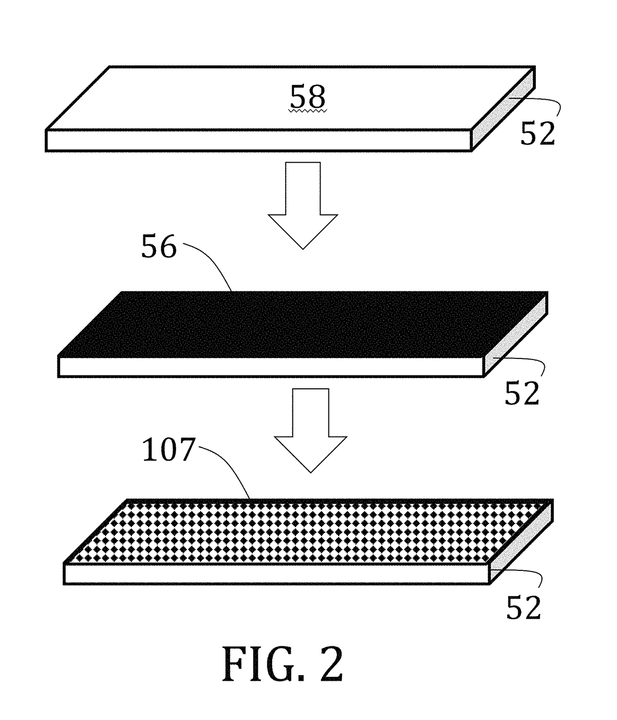
[0149]Glass microscope slides (50 mm×25 mm×1 mm) were first cleaned by successive washes of acetone and isopropanol to remove unwanted particulates. The clean slides were then plasma treated utilizing atmospheric air at a pressure of about 40 Pa ...
example 2
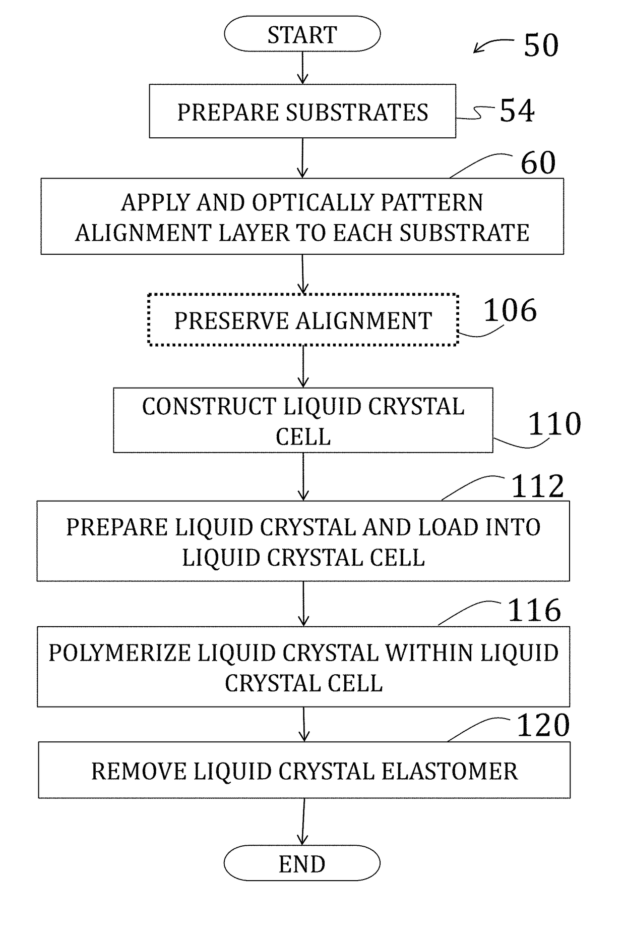
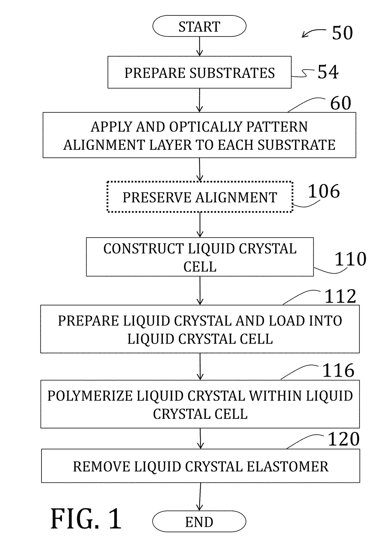
[0157]After preparing, patterning, and optionally coating two substrates as described in Example 1, the two substrates are arranged to be facing, spaced by 50 μm cylindrical spacers, and two edges were secured using a two-part epoxy to form a cavity therebetween. Alignment of the two substrates was performed under a polarizing optical microscope to ensure matching alignment of patterns of the substrates, and the two-part epoxy was cured at room temperature.
[0158]The cavity was then filled will liquid crystal comprising a mixture of 1.01:1 moles of RM82 to n-butylamine with 1 wt % of photoinitiator (DAROCURE® trimethylbenzoyl diphenylphosphine oxide (“TPO”), BASF SE, Ludwigshafen, Germany) by total monomer concentration. The solution, while being shielded from fluorescent light, was heated to melt solid components (temperature of about 70° C.) and mixed vigorously by vortex. The process was repeated at least three times and the resulting nematic mixture crystallized slowly at room te...
example 3
[0163]A Bruker FTIR (IFS 66 v / s) (Bruker Corp., Billerica, Mass.) in transmission mode was utilized to monitor the conversion of acrylate groups within the cavity of the cell of Example 2, after both stages of polymerization. Scans were performed from 400 cm−1 to 3200 cm−1 with a sampling interval of 4 cm−1. Data presented are an average of 32 scans. Oligomer mixtures were first dissolved in chloroform and then cast onto a PTFE IR sample card. Elastomer samples 50 μm thick were tested directly after polymerization. The peak at 812 cm−1 was utilized to monitor conversion of the acrylate carbon-carbon double bond and is presented as a function of time in FIG. 29. The first point utilized to monitor the reaction was after 6 hr at 75° C. After 18 hr, the conversion acrylate double bonds increased significantly. Upon further reaction (up to two weeks at 75° C.) the conversion did not significantly improve. As such, 18 hr was chosen for the length of the step-growth reaction.
PUM
| Property | Measurement | Unit |
|---|---|---|
| tensile strain | aaaaa | aaaaa |
| temperature | aaaaa | aaaaa |
| glass transition temperature | aaaaa | aaaaa |
Abstract
Description
Claims
Application Information