Cylindrical shaft-sealing material obtained from pile weave or knit

a technology of weave or knitted yarn and cylindrical shaft, which is applied in the direction of engine seals, leakage prevention, machines/engines, etc., can solve the problems of reducing seal performance, affecting the longevity of the seal, and viscoelasticity of the sealing member, so as to prevent powder leakage, facilitate the attachment, and eliminate the effect of pile entrainmen

Active Publication Date: 2018-02-27
SHOJI SUSUMU +1
View PDF14 Cites 0 Cited by
  • Summary
  • Abstract
  • Description
  • Claims
  • Application Information

AI Technical Summary

Benefits of technology

[0027]In accordance with a fifth means, because the cylindrical shaft seal member and the bearing are formed in such fashion that the cylindrical shaft seal member and the bearing which supports the rotating shaft and is a member which slides along the rotating shaft are constituted in integral fashion; the bearing portion and the shaft seal member that are constituted in integral fashion being such that structure is such that a space is provided for preventing pile from coming in contact with the bearing portion as a result of bulging or collapse of the pile; or structure being such that a cylindrical projection is provided which is different from the sliding portion of the bearing at an inside surface of this bearing, this cylindrical projection being constituted in integral fashion with respect to the cylindrical shaft seal member, deformation due to bulging or collapse of the pile or this cylindrical projection causing the fibers of the pile to bulge or collapse so as to be directed toward the interior along the direction of the rotating shaft, it is possible to eliminate entrainment of pile by the rotating shaft. Moreover, because the cylindrical shaft seal member is constituted in integral fashion with respect to the bearing to constitute a rotating shaft seal unit, it is possible in the event of failure to carry out replacement of the cylindrical shaft seal member by replacing the rotating shaft seal unit, so that replacement is accomplished not by replacing the entire apparatus but by replacing the component unit, there is reduced waste, resources are conserved, and there is improved efficiency during maintenance operations.

Problems solved by technology

Of these sealing members, rubber sealing members, being viscoelastic, have high coefficients of friction.
For this reason, rubber sealing members have produced heat at high rotational speeds, abrasion has caused decrease in seal performance, and there have been problems in terms of longevity.
Moreover, in accompaniment to production of heat due to friction, where the powder which is the material being sealed is a powder comprising resin as is the case with the toner in an electrophotographic apparatus, there has been the problem that the heat due to friction has caused the powder to soften and to adhere to the rotating shaft, causing the rotating apparatus of the electrophotographic apparatus to lock up.
Furthermore, at seals comprising contact produced by sealing member surfaces, increase in torque has caused problems in terms of longevity of the rotating apparatus.
However, because the sealing members have voids, powder which has entered the interior of the sealing member causes decrease in seal performance, and as is the case with rubber sealing members, there has been the problem that at high rotational speeds the heat due to friction causes the powdered resin which is the material being sealed to soften and to adhere to the rotating shaft, causing the rotating apparatus to lock up.
Moreover, with felt sealing members, because these employ felt which has been manufactured through compression of fibers, and because directionality of the fibers is irregular, it has been the case that once powder begins to enter the spaces between fibers within the sealing member, control of powder becomes impossible, and there has been occurrence of decrease in seal performance.
For this reason, because automatic insertion has been difficult, and a manual operation has been required, mechanization has been difficult to achieve.
However, as this cylindrical seal member is such that the slit which produces the springback is an inclined slit or a zigzag-shaped slit, because the tip of the cut portion produced by cutting in inclined or a zigzag fashion during manufacturing forms an acute angle, there are concerns with respect to safety during handling by workers.
Furthermore, because the cylindrical seal member is such that the shape thereof is not rectangular, punching must be carried out in an operation that takes place prior to when this is made to assume a cylindrical shape during fabrication, and so there have been problems in that there is loss of material as a result of punching and in that manufacturing time cannot be shortened.

Method used


Image

  • Cylindrical shaft-sealing material obtained from pile weave or knit
  • Cylindrical shaft-sealing material obtained from pile weave or knit
  • Cylindrical shaft-sealing material obtained from pile weave or knit

Examples


working examples

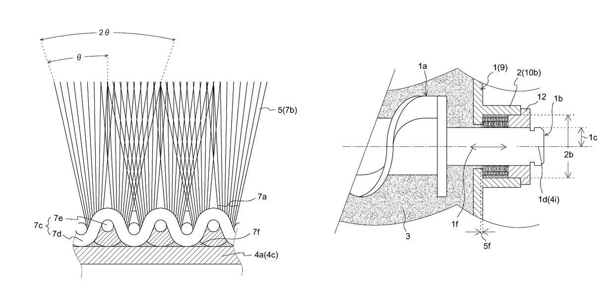
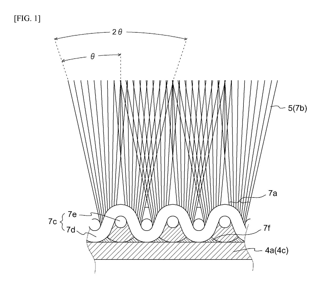
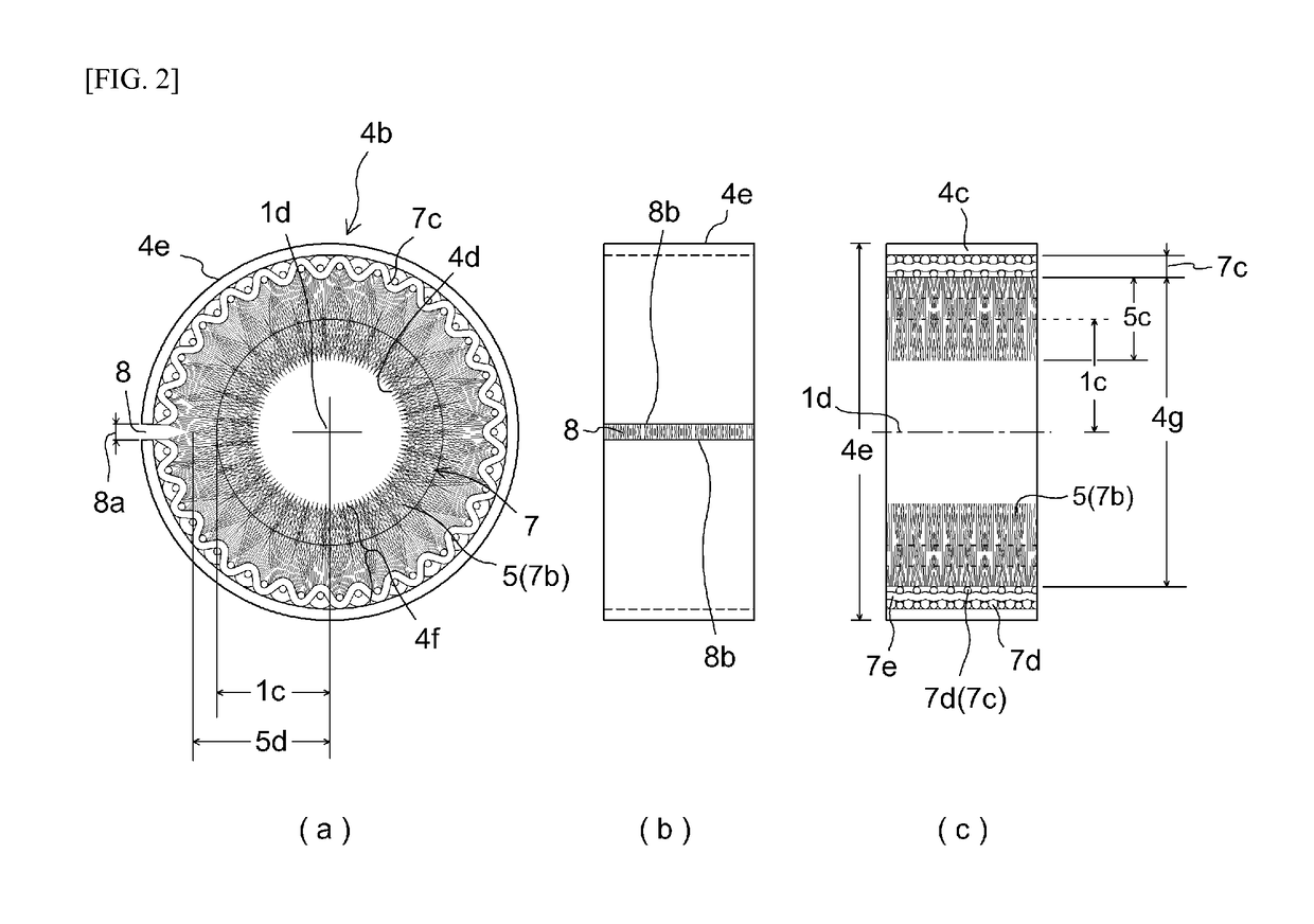
[0089]When hole diameter 10a for attachment of cylindrical shaft seal member 4b to hole 10 through which the rotating shaft passes is made to be 10 mm, it is caused to be attached to this hole diameter 10a. To this end, when length of pile 5 was 2 mm, thickness of ground yarn 7c at woven / knit pile fabric 7 was 0.9 mm, fiber density at pile 5 was 467500 threads per in2, and average pile diameter ΦF was 13 μm, planar seal member 4f comprising this woven / knit pile fabric 7 was laminated by means of adhesive to an aluminum sheet of thickness 0.3 mm constituting cylindrical support member 4c of outside diameter 4b, this was cut to a width of 3 mm and a length of 29.8 mm to accommodate hole 10 through which the rotating shaft passes, and this was then formed by means of a forming machine to fabricate cylindrical shaft seal member 4b. Note that when this was attached to attachment hole 2a for which diameter 10a of the hole through the rotating shaft passes was 10 mm, gap 8c at linear slit ...


PUM


Abstract

A rotational shaft seal member which does not cause leakage of powder and which has a slit capable of being enlarged as a result of occurrence of springback. Cylindrical shaft seal member 4b at powder container 1 includes pile 5 including woven / knit pile fabric 7 having cut pile 7b at the inside of cylindrical shaft seal member 4b and pile cylindrical support member 4c; the outside diameter 4e being capable of shrinkage as a result of external pressure, and being capable of enlargement as a result of pressure on the inside diameter 4d. When cylindrical shaft seal member 4b is inserted in attachment hole 2a of support frame 2 at the rotating body, attachment is achieved because slit 8 causes shrinkage of outside diameter 4e of cylindrical shaft seal member 4b, enlargement due to springback of slit 8 causing intimate contact with attachment hole 2a.

Description

TECHNICAL FIELD[0001]This invention relates to a cylindrical shaft seal member comprising woven pile fabric and / or knit pile fabric (woven pile fabric and / or knit pile fabric is hereinafter referred to as “woven / knit pile fabric”) having cut pile formed at an inside of a cylindrical support member that seals an end of a rotating shaft which is a rotating body in a device that handles powder, and in particular relates to a cylindrical shaft seal member in which springback causes there to be no occurrence of leakage of powder from an end of a cylindrical shaft.BACKGROUND ART[0002]Rubber sealing members, sponge sealing members, and felt sealing members have conventionally been employed as sealing members to seal ends of rotating shafts which are rotating bodies in devices that handle powder. Of these sealing members, rubber sealing members, being viscoelastic, have high coefficients of friction. For this reason, rubber sealing members have produced heat at high rotational speeds, abras...

Claims


Application Information

Patent Timeline
Patent Type & Authority Patents(United States)
IPC IPC(8): F01D11/02F16J15/3288F16J15/3268
CPCF16J15/3268F16J15/3288
Inventor SHOJI, SUSUMUFUKUI, KAZURO
Owner SHOJI SUSUMU
Why Eureka
Try Eureka