System and method for wind turbine sensor calibration

a wind turbine and sensor technology, applied in the field of system and method for wind turbine sensor calibration, can solve problems such as measurement errors, and achieve the effect of high degree of accuracy and reliability

Active Publication Date: 2018-03-06
LM WP PATENT HLDG
View PDF31 Cites 5 Cited by
  • Summary
  • Abstract
  • Description
  • Claims
  • Application Information

AI Technical Summary

Benefits of technology

[0019]Wind turbine tower bending during turbine operation can result in measurement errors during the operation of a wind turbine sensor system, such as a blade deflection monitoring system. Furthermore, tower bending can influence the calculation of an accurate blade-to-tower clearance distance. Accordingly, the provision of a suitable calibration system to calibrate the operation of a turbine sensor system such as an integrated blade deflection monitoring system results in a more reliable and accurate performance of the sensor system and any associated wind turbine control systems. The use of external optical devices provides a relatively simple and easily verifiable method of calibrating tower bending during load for a wind turbine tower.
[0020]The method can also be used as a method of verification of the output of a wind turbine sensor system, by providing a relatively simple and accurate method for verifying the true position of a wind turbine tower and / or a wind turbine blade experiencing deflection, and which can be relatively easily implemented on a wind turbine using straightforward and readily available components.
[0028]By monitoring the blade deflection during a measured load condition, a sensor system such as a deflection monitoring system can be accurately calibrated for future turbine operation.
[0037]Monitoring the tower deflection and / or the blade deflection for no-load conditions provides a useful baseline measurement which can be used for accurate calibration of a sensor system such as a deflection monitoring system.
[0039]The use of such wireless distance monitoring systems provides for a high degree of accuracy and reliability during the operation of the deflection monitoring system. As the calibration system is based on an optical detection of position, this provides a second layer of security when initially calibrating the deflection monitoring system, as the calibration operation can be based on two separate measurements of position—the output of the calibration system and the output of the deflection monitoring system itself. It will be understood that the wind turbine blade may comprise an alternate deflection monitoring system, e.g. a fibre-optic deflection monitoring system, and accelerometer-based system, etc.

Problems solved by technology

Wind turbine tower bending during turbine operation can result in measurement errors during the operation of a wind turbine sensor system, such as a blade deflection monitoring system.

Method used


Image

  • System and method for wind turbine sensor calibration
  • System and method for wind turbine sensor calibration
  • System and method for wind turbine sensor calibration

Examples


Embodiment Construction

[0063]Embodiments of the invention will now be described, by way of example only, with reference to the accompanying drawings, in which:

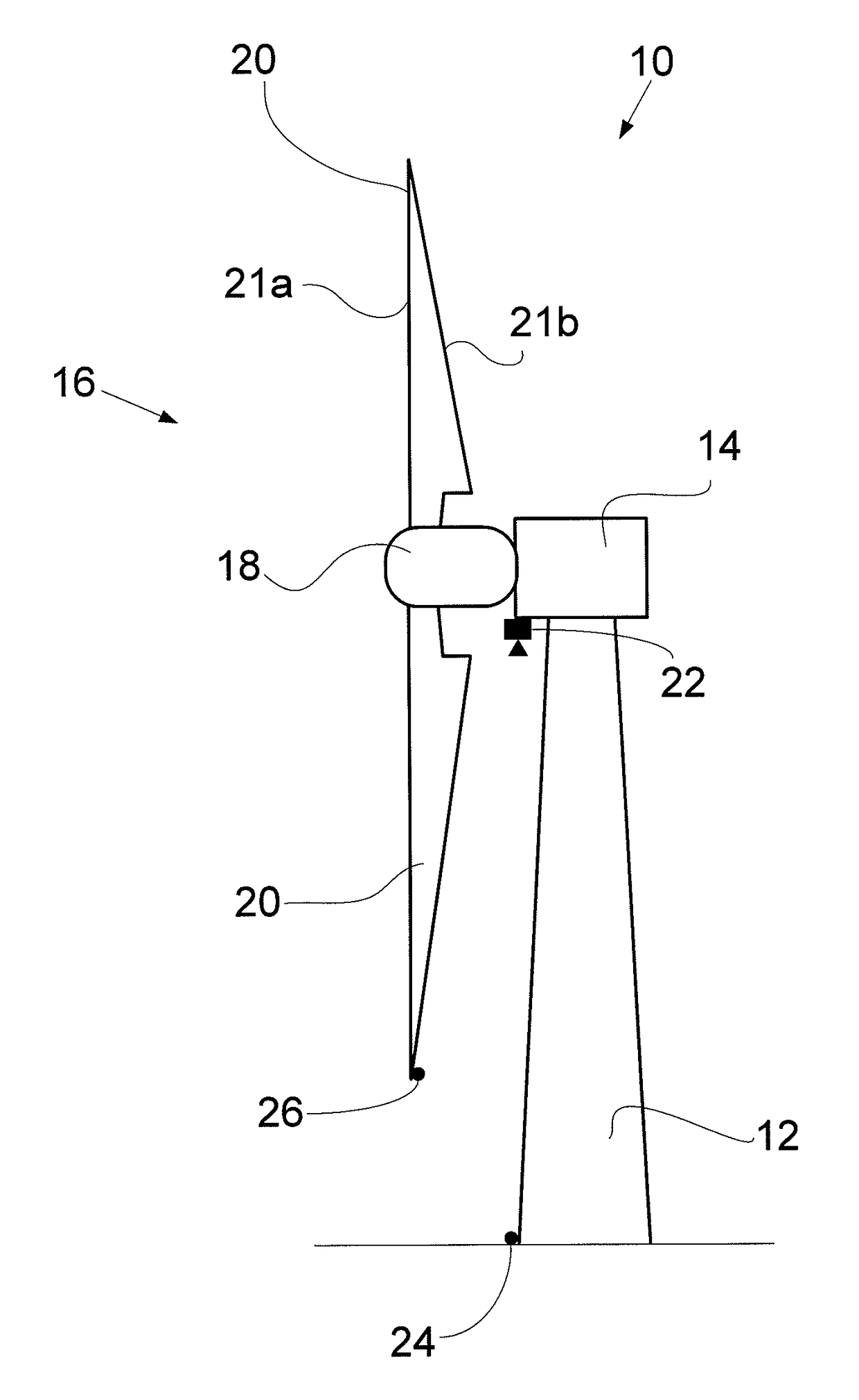
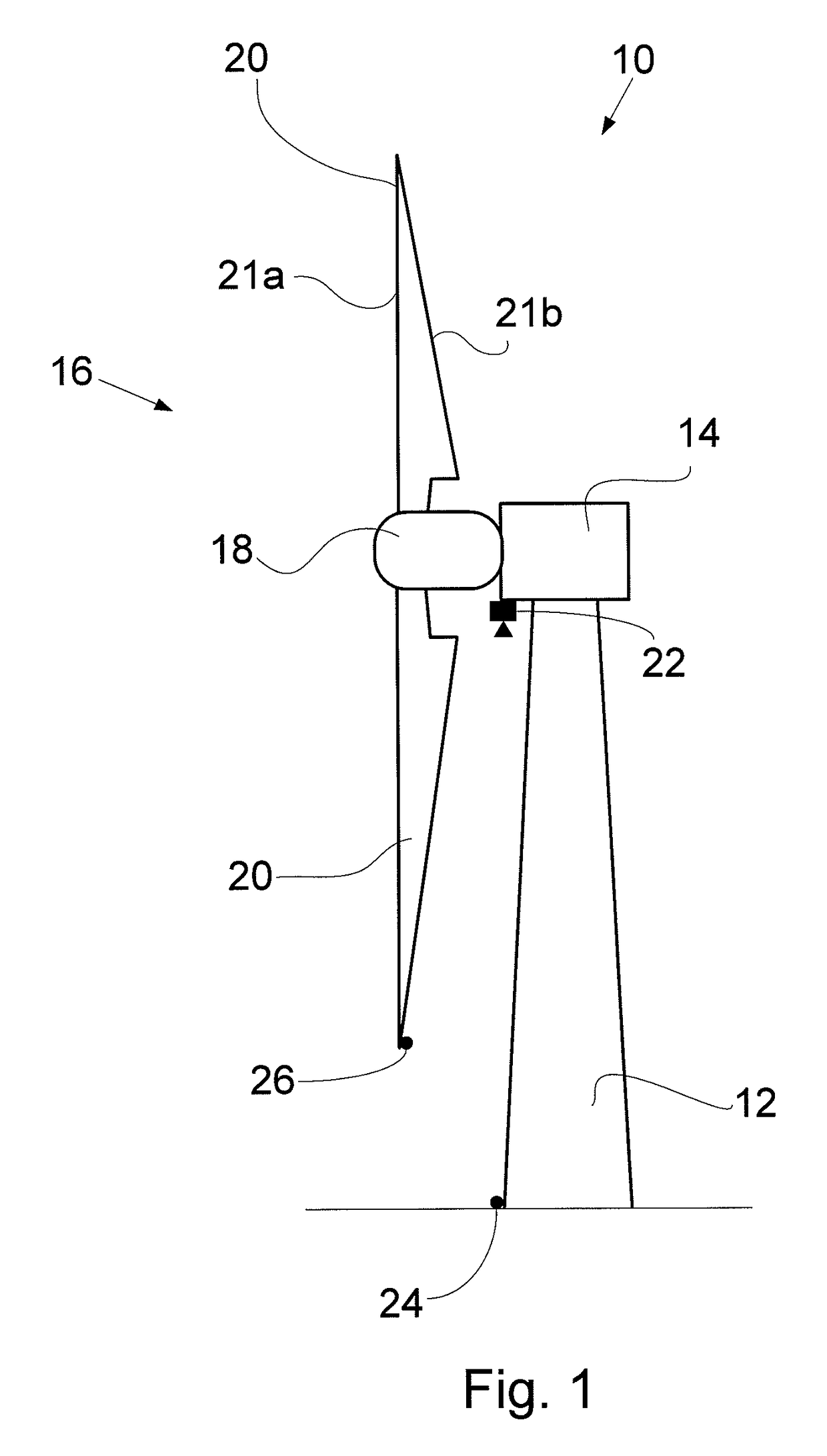
[0064]FIG. 1 shows a wind turbine having a calibration and verification system according to the invention;

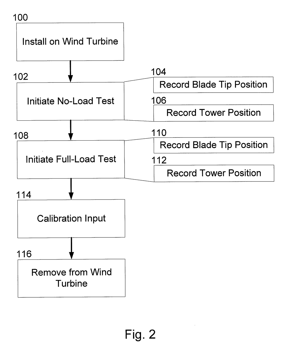
[0065]FIG. 2 illustrates the steps of a calibration method according to an aspect of the invention;

[0066]FIG. 3 illustrates a method of verification and tuning of a sensor system according to an aspect of the invention; and

[0067]FIG. 4 illustrates an example of data recorded using an embodiment of the system and method of the invention.

[0068]It will be understood that the attached drawings are illustrative only, and are not provided to scale.

[0069]With reference to FIG. 1, an upwind horizontal axis wind turbine 10 is illustrated according to the so-called “Danish concept”. The wind turbine 10 comprises a wind turbine tower 12, a nacelle 14 provided at the top of said tower 12, and a wind turbine rotor 16 rotatably provided on said nacelle 14. Th...


PUM


Abstract

A system and method for the verification and calibration of wind turbine sensor systems is provided. The system comprises an optical capture device provided on a wind turbine which is arranged to record the position of at least one light source provided at the wind turbine during operation of the wind turbine. The motion of the light source relative to the optical capture device can provide an indication of relative motion of a portion of the wind turbine during operation, which can then be used as an input to a calibration and / or a verification system for a sensor system of the wind turbine.

Description

[0001]This is a National Phase Application filed under 35 U.S.C. 371 as a national stage of PCT / EP2013 / 076285, filed Dec. 11, 2013, an application claiming the benefit of United Kingdom Application No. 1222540.5, filed Dec. 14, 2012, the content of each of which is hereby incorporated by reference in its entirety.FIELD OF THE INVENTION[0002]The present invention relates to a system and method for the calibration and / or verification of a wind turbine sensor system.BACKGROUND OF THE INVENTION[0003]In modern wind turbine design, a continued drive for increased efficiency and reliability has led to a desire to provide more intelligent solutions for wind turbine control systems. Such solutions often involve the incorporation of wind turbine sensor systems integrated into the turbine design stage. Such systems can produce relatively accurate outputs, as they can be integrated with the manufacture of the wind turbine components, e.g. a blade deflection monitoring system inlaid within the s...

Claims


Application Information

Patent Timeline
Patent Type & Authority Patents(United States)
IPC IPC(8): F01D25/00F04D29/00F03D17/00F03D7/02
CPCF03D17/00F03D7/022Y02E10/726F05B2270/802F05B2270/8041F05B2270/33Y02E10/72
Inventor KLITGAARD, MICHAELBAEK, PETERBYSKOV, CLAUS
Owner LM WP PATENT HLDG
Why Eureka
Try Eureka