Method for simultaneous capture of image data at multiple depths of a sample

a sample and image data technology, applied in the field of sample capture, can solve the problems of reducing the fill factor of the pixel and the relative low speed of reading out the region, and achieve the effects of maximizing the photo active part of the pixel, maximizing the fill factor, and optimizing efficiency

Active Publication Date: 2018-03-06
KONINKLJIJKE PHILIPS NV
View PDF5 Cites 0 Cited by
  • Summary
  • Abstract
  • Description
  • Claims
  • Application Information

AI Technical Summary

Benefits of technology

[0010]Therefore, a read-out method for generating seamless 2D or 3D images while changing capture depth during the scanning is presented. This allows a fast image acquisition of not perfectly flat and / or volumetric samples and can be specifically applied in digital slide scanners, e.g. for digital pathology, but also in other technical fields. With this method it is possible to capture a seamless image, which would not be possible without the temporary dual, i.e., simultaneous readout, because a change in line sensor results not only in a change of acquisition depth, but also in a translation along the scan direction. This latter translation causes either a gap in the image, or a repetition of image data. The method as described before is necessary to prevent the gap. For the repetition, part of the image data can be discarded, but no dual acquisition is needed. It is important to stress, that this method would also be required when changing ROI in a conventional 2D CMOS sensor when it's used for the purpose of a 2D autofocus system. This is because any change in the ROI that leads to an effective change in acquisition depth will also lead to a translation along the scan direction, if the 2D CMOS sensor is tilted with respect to the optical axis. This translation along the scan direction will need to be compensated, if an undistorted final image is to be obtained. The present invention avoids such distortions as explained herein. The presented method can be automatically carried out by an imaging device as disclosed herein.
[0011]Of course more lines of pixels than the first and second line can be used by this method for capturing image data. As can easily be gathered from the embodiment examples shown in FIGS. 3 to 5, a large plurality of pixel lines / line sensors, which are all respectively offset from each other, can be used.
[0016]Thus, a novel method is disclosed to allow for the simultaneous capture of image data from multiple depths of a volumetric sample. The method allows for the seamless acquisition of a 2D or 3D image, while changing on the fly the acquisition depth in the sample. This method can also be used for auto focusing. Additionally this method of capturing image data from the sample allows for optimal efficiency in terms of speed, and light sensitivity, especially for the herein mentioned purpose of 2D or 3D imaging of samples when using a tilted configuration as depicted in FIG. 2.
[0017]For example, this method can be applied by an imaging sensor of an imaging device which combines multiple TDI line sensors on a single die, which will be explained in detail in the context of the embodiments shown in FIGS. 3 to 5. There, the TDI line sensors are separated by a gap. Such a sensor may have a dual (TDI) read-out engine, which allows efficient reading out of at least two line sensors at maximum speed and sensitivity. The improvement over a conventional 2D sensor of the same size and resolution achieved by this novel design and read out method is twofold. First, the gap between the photo sensitive parts / lines of pixels (the TDI linesensors) can be used to put the logic and connective circuitry of the sensor. This allows for maximizing the photo active part of the pixels in the photo sensitive area of the sensor, i.e. maximize the fill factor. This allows for a sensitive sensor without microlenses that are common on 2D CMOS sensors. Avoiding micro-lenses is important for placing the sensor tilted in the optical path. Second, the gap allows for faster read-out because more circuitry can be on the sensor in the gap, allowing for a faster read out method and a faster sensor.
[0019]The method of simultaneous capture of image data at multiple depths of a sample overcomes two problems that result from normal imaging methods using a normal 2D CMOS sensor for the autofocus and 3D imaging. On the one hand low light sensitivity due to low fill factor of pixels in a normal 2D CMOS sensor can be improved. This is normally overcome with micro-lenses, but micro-lenses are not suitable for use when the sensor is tilted with respect to the optical path as shown in FIG. 2. Moreover, the low speed in ROI read-out of normal 2D CMOS sensors can be increased by the present invention as more read-out electronics can placed in the spaces between first pixel line and the second pixel line, as described in more detail, for example, in the context of FIGS. 4 and 5.
[0023]According to another exemplary embodiment of the present invention the simultaneous capturing of the second image and the third image is carried out for as long as it takes to bridge the offset between the first pixel line and the second pixel line during scanning. Therefore, the read-out method generates seamless 2D or 3D images while changing capture depth during the scanning. Clearly, this allows a fast image acquisition of not perfectly flat and / or volumetric samples. The calculation to determine how long it takes to bridge the respective offset can be done by the skilled person without a problem. Starting from the distance between the two cameras, i.e., the two pixel lines, in projection one knows to how many pixels the distance relates. With the exposure frequency, i.e., the line rate, one knows how many pixels are in the offset / gap. In another exemplary embodiment it is also possible to do real time detection if for example the sample position might fluctuate during scanning. One example that might require real time detection would be the case where there is no scanning, but a flow in a fluid. This flow might be less regular, which means that it's not a fixed amount of exposures before the gap is bridged. The real time detection in this case would be tracking of the object's lateral position as it flows by.

Problems solved by technology

However, such non-photosensitive parts of the pixel reduce the fill factor of the pixel which is especially harming during low light conditions.
In addition, currently available imaging sensors provide for a relative low speed in reading out the region of interest (ROI) as only a limited number of read out electronics can be provided within the limited space of a given pixel size.

Method used


Image

  • Method for simultaneous capture of image data at multiple depths of a sample
  • Method for simultaneous capture of image data at multiple depths of a sample
  • Method for simultaneous capture of image data at multiple depths of a sample

Examples


Embodiment Construction

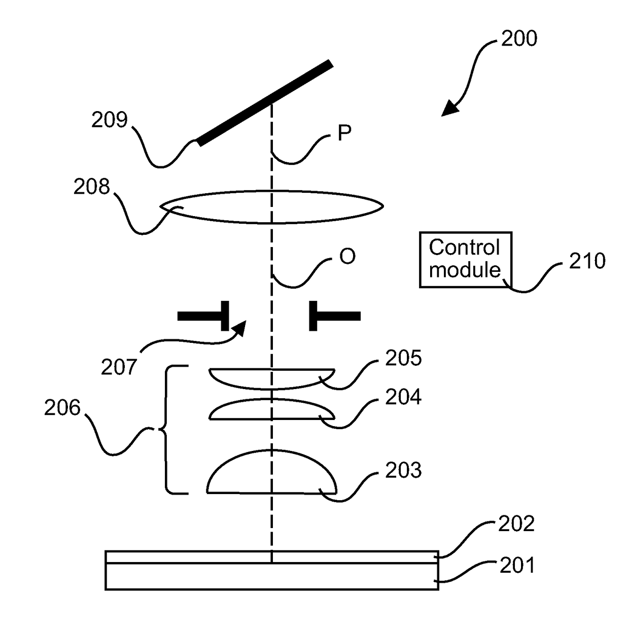
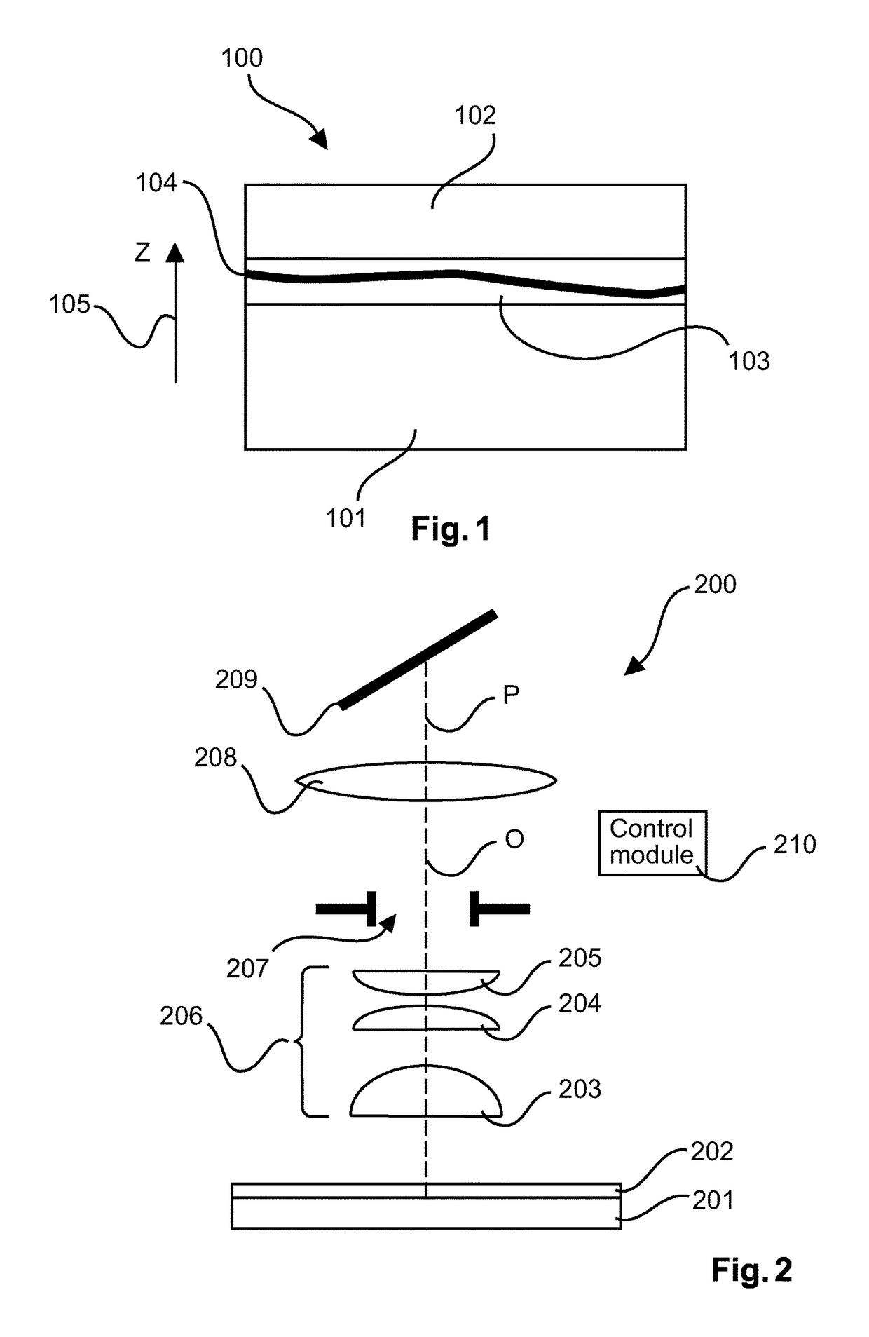
[0044]According to an exemplary embodiment of an imaging system of the present invention a scanning microscope 200 is shown within FIG. 2. The imaging system 200 can carry out the method for simultaneous capture of image data at multiple depths of the sample as described herein. Particularly, the imaging system 200 is configured for carrying out the steps S1 to S5 as disclosed in the context of FIG. 6. However, it is important to note that the imaging system 200 allows for a read-out method for generating seamless 2D or 3D images while changing capture depth during the scanning. This allows a fast image acquisition of not perfectly flat and / or volumetric samples. With this method and imaging system 200 it is possible to capture a seamless image, which would not be possible without the temporary dual, i.e., simultaneous readout, because a change in line sensor results not only in a change of acquisition depth, but also in a translation along the scan direction. This latter translatio...


PUM


Abstract

A novel method is disclosed to allow for the simultaneous capture of image data from multiple depths of a volumetric sample. The method allows for the seamless acquisition of a 2D or 3D image, while changing on the fly the acquisition depth in the sample. This method can also be used for auto focusing. Additionally this method of capturing image data from the sample allows for optimal efficiency in terms of speed, and light sensitivity, especially for the herein mentioned purpose of 2D or 3D imaging of samples when using a tilted configuration as depicted in FIG. 2. The method may be particularly used with an imaging sensor comprising a 2D array of pixels in an orthogonal XY coordinate system where gaps for electronic circuitry are present. Also other imaging sensor may be used. Further, an imaging device is presented which automatically carries out the method.

Description

CROSS-REFERENCE TO PRIOR APPLICATIONS[0001]This application is the U.S. National Phase application under 35 U.S.C. § 371 of International Application No. PCT / EP2015 / 079331, filed on Dec. 11, 2015, which claims the benefit of European Patent Application No. 14199531.6, filed on Dec. 22, 2014. These applications are hereby incorporated by reference herein.FIELD OF THE INVENTION[0002]The present invention relates to the field of imaging a sample, and applies advantageously in the field of digital pathology.[0003]In particular, the present invention relates to a method for simultaneously capturing image data at multiple depths of a sample and to an imaging system for simultaneous capture of image data of a sample at multiple depths.BACKGROUND OF THE INVENTION[0004]A digital scanning microscope usually makes a digital image of a sample such as a tissue sample placed in a microscope slide. This is typically done by scanning the sample over the whole microscope slide and stitching differen...

Claims


Application Information

Patent Timeline
Patent Type & Authority Patents(United States)
IPC IPC(8): H04N13/00G02B21/00G02B21/22G02B21/36
CPCG02B21/367H04N13/0217G02B21/22G02B21/002G02B21/365H04N13/218
Inventor HULSKEN, BAS
Owner KONINKLJIJKE PHILIPS NV
Why Eureka
Try Eureka