High voltage, high efficiency sine wave generator with pre-set frequency and adjustable amplitude

a sine wave generator and high-efficiency technology, applied in the direction of digital data processing details, pulse automatic control, instruments, etc., can solve the problems of reducing battery life, complicating device design, and reducing heat loss by close to 50%

Active Publication Date: 2018-03-06
NOVOCURE GMBH
View PDF2 Cites 49 Cited by
  • Summary
  • Abstract
  • Description
  • Claims
  • Application Information

AI Technical Summary

Problems solved by technology

The use of linear amplifier results in heat losses of close to 50%, reducing battery life, and complicating device design because a cooling system is required to dissipate the heat generated.
However, existing Class-D amplifier technology is not suitable for this task for two reasons.
First, the signal distortion associated with Class-D amplifiers increases as the signal amplitude decreases, and TTFields requires sinewaves with very low levels of distortion at all signal levels.
This requires very fast switches and complex control that are currently unavailable.

Method used


Image

  • High voltage, high efficiency sine wave generator with pre-set frequency and adjustable amplitude
  • High voltage, high efficiency sine wave generator with pre-set frequency and adjustable amplitude
  • High voltage, high efficiency sine wave generator with pre-set frequency and adjustable amplitude

Examples


first embodiment

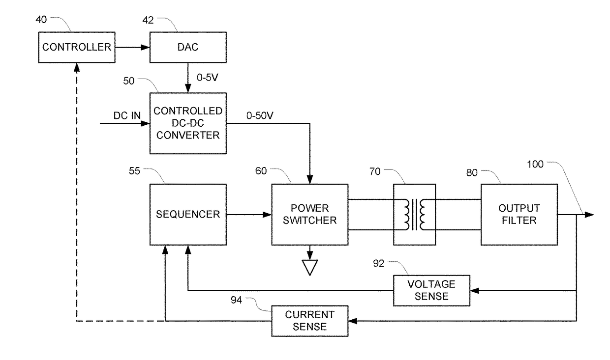
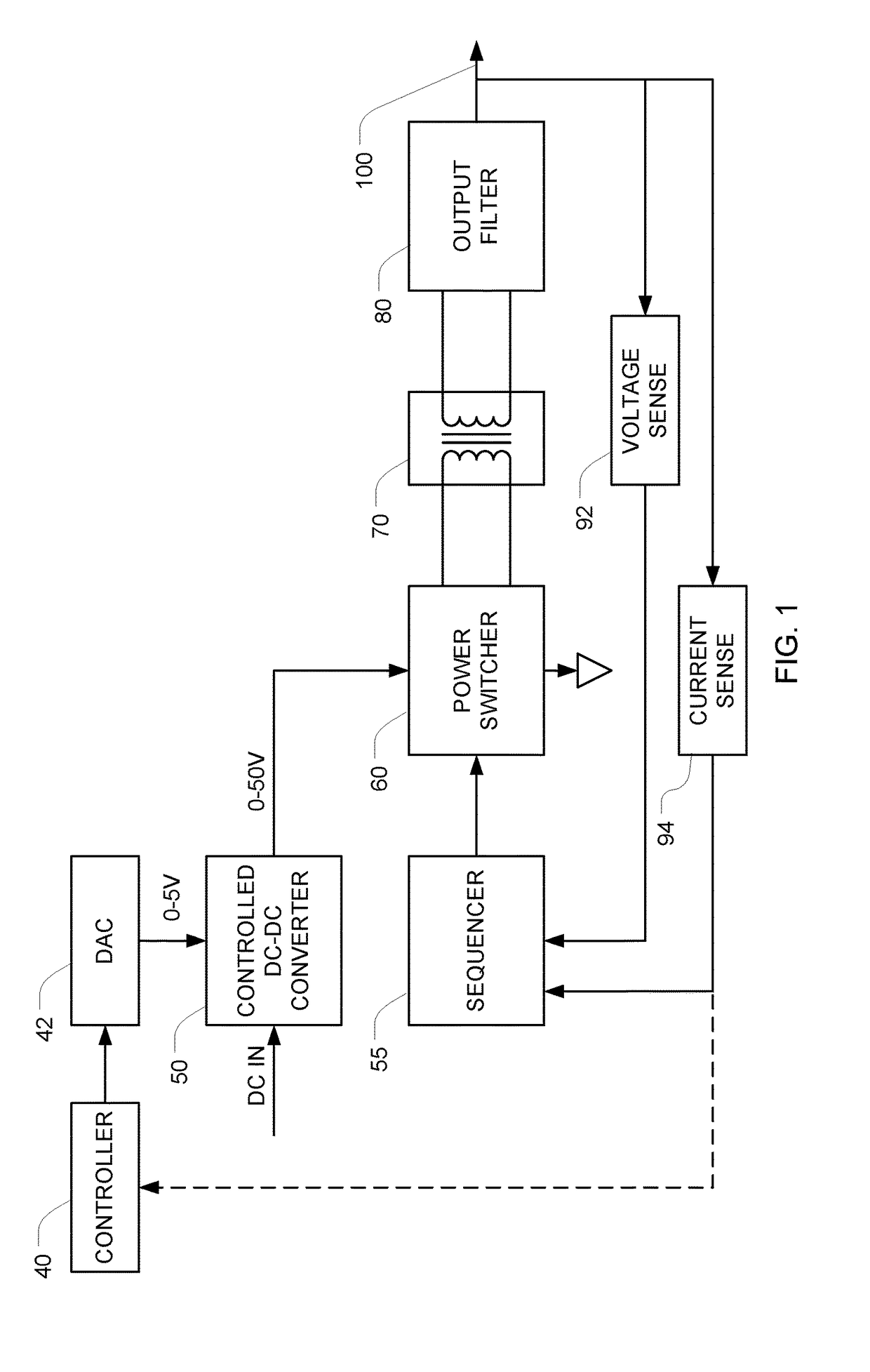
[0040]FIG. 1 is a block diagram of a sinusoid generator that generates a sinusoid at a pre-set frequency f, with a controllable amplitude. Ultimately, the amplitude of the output sinusoid will be proportional to the output of the DC power source 50, which is preferably a controlled DC-DC converter.

[0041]In the illustrated embodiment, the DC to DC converter 50 is configured to multiply an analog voltage-control input signal by 10, so when a 1 V voltage-control signal is applied the output will be 10 V, and when a 5 V voltage-control signal is applied the output will be 50 V, with proportional control there between. The output of the DC-DC converter 50 can therefore take any value between 0 and 50 V, depending on the voltage (e.g., 0-5 V) that is applied to the analog voltage-control input. A controller 40 controls the output voltage of the DC-DC converter 50 by writing a control word to a digital-to-analog converter (DAC) 42. The DAC 42 then generates an analog voltage that is propor...

second embodiment

[0068]FIG. 5 is a block diagram of a sinusoid generator that generates a sinusoid at a pre-set frequency f, with controllable amplitude, in which n=2. As a result, there are two DC-DC converters 50, 50B and (following the formula N=2+4n) 10 samples per cycle are used. Note that in the FIG. 5-6 embodiment, components with similar reference numbers operate in a manner similar to the description above in connection with the FIG. 1-2 embodiment.

[0069]FIG. 7 depicts a sine wave 120 and an oversampled version of that sine wave 122 that is sampled 10 times per cycle (i.e., at 0°, 36°, 72°, . . . 324°, and 360°). Looking at this oversampled version 112, it becomes apparent that it contains only five voltage levels: a low positive voltage +V1, a higher positive voltage +V2, a low negative voltage −V1, a higher negative voltage −V2, and zero volts (between 0° and 36° and also between 180° and 216°). Here again, the zero Volt level exists because we have chosen the sampling times such that one...


PUM


Abstract

An apparatus for generating a sinusoid at a pre-set frequency f includes a DC power source with a controllable output voltage, a transformer, a power switch, a sequencer, and an output filter. The power switch is configured to apply the output of the DC power source to the primary of the transformer in either direction or to remain off based on control signals that are applied to its control input. The sequencer applies control signals to the control input in a choreographed sequence to form an oversampled version of a sine wave. The output filter is connected to the secondary of the transformer, and it passes the pre-set frequency f and attenuates frequencies above a cut-off frequency. In some preferred embodiments, the cut-off frequency is 3f and the transfer function of the output filter has a zero at 5f.

Description

CROSS REFERENCE TO RELATED APPLICATIONS[0001]This Application claims the benefit of U.S. Provisional Application 62 / 232,762 filed Sep. 25, 2015, which is incorporated herein by reference in its entirety.BACKGROUND[0002]Class-D amplifiers are electronic amplifiers in which the amplifying device operates as an electronic switch, instead of as linear gain devices as in other amplifiers. In class-D amplifiers, the analog signal is amplified using a system of switches that convert the signal into a series of pulses by pulse width modulation, pulse density modulation or another method. The pulses that make up the amplified signals are then passed through a low pass filter that filters out the high frequency signal components to form an amplified version of the original signal. The filter is constructed from capacitive and inductive elements so that the energy losses associated with the filter are low. Class-D amplifiers are designed to track the input signal in real-time, and usually work...

Claims


Application Information

Patent Timeline
Patent Type & Authority Patents(United States)
IPC IPC(8): H03L5/00H02M7/5387G06F1/02H02M1/12H02M5/12H02M7/493
CPCG06F1/022H02M1/126H02M7/53871H02M5/12H02M2007/53878H02M7/493G06F1/0321H02M7/53878
Inventor WASSERMAN, YORAMLANGERMAN, EDWARDSHTOTLAND, MIKHAILKIRILLOV, SERGEIKRINITSKY, MICHAELKAIKOV, VICTOR
Owner NOVOCURE GMBH
Why Eureka
Try Eureka