
Braking distance control device

a control device and braking distance technology, applied in the direction of automatic initiation, braking system, transportation and packaging, etc., can solve the problems of overheating of the brake device, deterioration due to friction and heating, etc., and achieve the effect of reducing the braking distan

Active Publication Date: 2018-03-13
NIHON KENKI CO LTD
View PDF23 Cites 1 Cited by
  • Summary
  • Abstract
  • Description
  • Claims
  • Application Information

AI Technical Summary

Benefits of technology

[0008]According to the present invention, the increase in the braking distance can be reduced appropriately depending on the situation.

Problems solved by technology

When the braking distance increases and the braking time extends significantly, overheating of brake devices can occur especially in cooled brake devices such as the electric and mechanical brake devices and deterioration due to friction and heating can occur especially in the hydraulic and mechanical brake devices.

Method used


Image

  • Braking distance control device
  • Braking distance control device
  • Braking distance control device

Examples


first embodiment

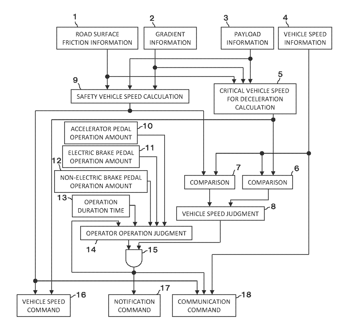
[0018]FIG. 1 is a functional block diagram of a braking distance control device according to a first embodiment of the present invention.

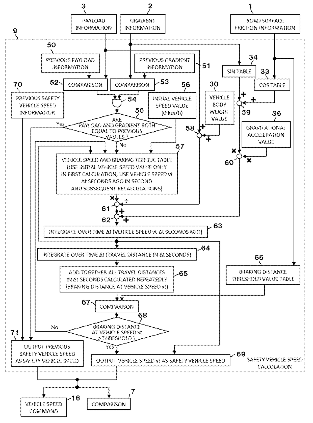
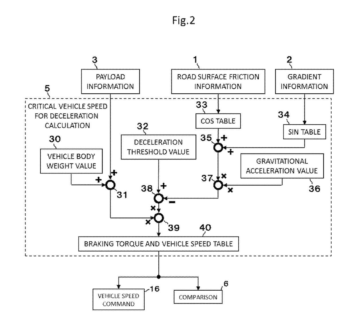
[0019]The braking distance control device shown in FIG. 1 is employed for an electrically driven work vehicle, such as a dump truck, that includes an AC generator driven by a prime mover and at least two travel electric motors (for driving rear wheels, for example) driven by electric power supplied from the AC generator, and that is braked by an electric braking device using torque generated by the electric motors. The braking distance control device includes information acquisition units 1 to 4 and 10 to 13, a critical vehicle speed for deceleration calculation unit 5, a safety vehicle speed calculation unit 9, a vehicle speed judgment unit 8, an operator operation judgment unit 14, a logical product calculation unit 15, a vehicle speed command unit 16, a notification command unit 17 and a communication command unit 18 as its main components. Thes...

second embodiment

[0059]FIG. 7 is a functional block diagram of a braking distance control device according to a second embodiment of the present invention.

[0060]The braking distance control device according to this embodiment differs from that according to the first embodiment in further having a function of controlling the brake devices. The braking distance control device of this embodiment includes information acquisition units 80 and 81, a non-electric brake braking distance calculation unit 82, a non-electric brake control unit 86 and an electric brake control unit 87 in addition to the components constituting the braking distance control device of the first embodiment. Explanation of components equivalent to those in the first embodiment is omitted here. The additional components will be explained in turn below.

1. Information Acquisition Units 80 and 81

[0061]The information acquisition units 80 and 81 are means for acquiring control vehicle speed information and vehicle speed controllability i...


PUM


Abstract

A braking distance control device employed for an electrically driven work vehicle includes a safety vehicle speed calculation unit that calculates a safety vehicle speed at which a braking distance provided by use of an electric brake device becomes less than or equal to a threshold value, based on gradient information, payload information, road surface friction information, vehicle speed information, and a braking torque characteristic of electric motors: a critical vehicle speed for deceleration calculation unit that calculates a critical vehicle speed for deceleration at which deceleration provided by use of the electric brake device becomes less than or equal to a threshold value; and an operation judgment unit 14 that judges a setting of notification, based on pedal operation amounts.

Description

TECHNICAL FIELD[0001]The present invention relates to a braking distance control device for reducing the increase in the braking distance of an electrically driven work vehicle that travels by the driving of drive wheels with electric motors.BACKGROUND ART[0002]There have been known electrically driven vehicles of a hybrid type in which a generator is driven by an engine and electric power generated by the generator is supplied to a motor for rear wheels to drive the rear wheels. When such an electrically driven vehicle of the hybrid type travels at high speed, the motor torque drops due to the increase in the revolution speed of the motor, and the braking distance of the vehicle can increase significantly especially when the vehicle carries a heavy load and travels on a downward slope or the like. When the braking distance increases, it is common to brake the vehicle by also using one of an exhaust brake device, a hydraulic brake device and a mechanical brake device in addition to ...

Claims


Application Information

Patent Timeline
Patent Type & Authority Patents(United States)
IPC IPC(8): B60T8/72B60T8/52B60L7/26B60L11/08B60T8/172B60T8/18B60T8/24B60L50/13B60L50/15
CPCB60T8/72B60L7/26B60L11/08B60T8/172B60T8/245B60T8/52B60T8/18B60T2220/04B60T2210/12B60T7/12B60T8/17B60L7/24B60W10/04B60W10/08B60W10/18B60W10/184B60W30/18127B60L50/13B60L50/15
Inventor TAKEDA, KOEISAITO, SHINJIRO
Owner NIHON KENKI CO LTD
Learn More