Sector-based clock routing methods and apparatus

a clock routing and sector-based technology, applied in the field of sector-based clock routing methods, can solve the problems of circuit operation incorrectly, clock skew, and problems for both hold time and setup time constraints, and achieve the effect of reducing the size or the height of the h-tr

Active Publication Date: 2018-03-20
ALTERA CORP
View PDF4 Cites 10 Cited by
  • Summary
  • Abstract
  • Description
  • Claims
  • Application Information

AI Technical Summary

Benefits of technology

[0010]Therefore, in accordance with embodiments of the present invention there is provided a clock-tree construction method for a configurable clock grid structure having a plurality of sectors and a plurality of wire segments. The method includes defining a clock region within the clock grid structure. The method further includes constructing an H-tree that covers the clock region, and aligning the clock region within the one or more H-trees. The method further includes reducing a size or a height of the H-tree to generate a clock tree.

Problems solved by technology

Clock skew is caused by the unequal delay of the clock signals through different paths in the clock tree from the root to the leaves.
Clock skew can cause problems for both hold time and setup time constraints.
When the hold time constraint is violated, the circuit operates incorrectly.
When the setup time constraint is violated, the circuit may operate correctly if the clock frequency is reduced, but the performance of the circuit may be compromised.
In addition, cross-talk between wires can also introduce delay variations.
Known skew may be compensated for when constructing the circuit, but it is difficult to evaluate and compensate for unknown skew.
For example, timing analysis tools may build in margin for both hold and setup time constraints to account for unknown skew, and such skew may reduce the performance of the circuit.
Such a path incurs a performance loss that is the maximum clock loss of the clock tree.

Method used


Image

  • Sector-based clock routing methods and apparatus
  • Sector-based clock routing methods and apparatus
  • Sector-based clock routing methods and apparatus

Examples


Embodiment Construction

[0032]Unless otherwise indicated, the discussion that follows will be based on an example of a programmable integrated circuit device such as a Field-Programmable Gate Array (FPGA). However, it should be noted that the subject matter disclosed herein may be used in any kind of fixed or programmable device, including, but not limited to, an application-specific integrated circuit (ASIC).

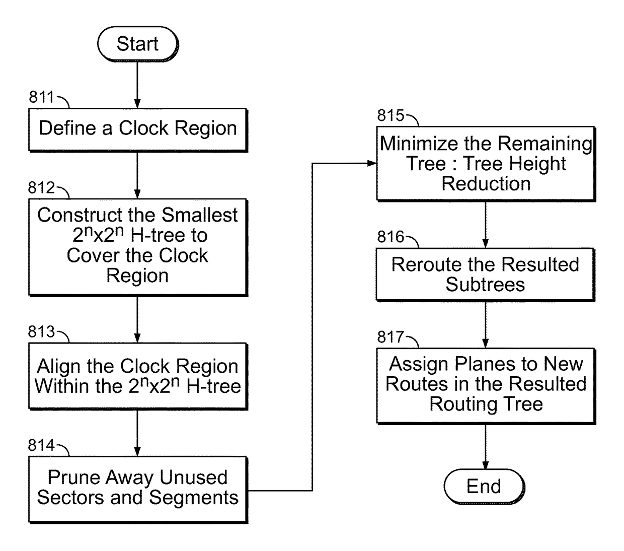
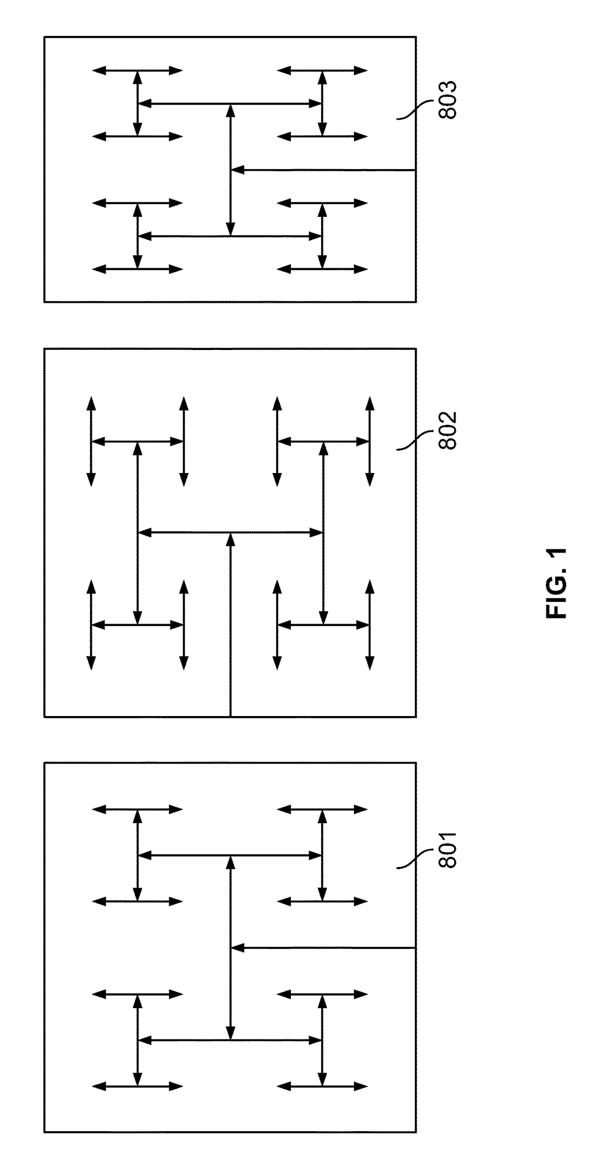
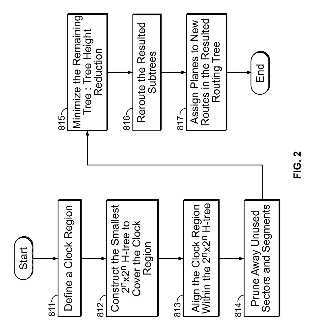
[0033]In some embodiments of the invention, the discussion that follows describes a variety of methods for constructing clock trees using a configurable clock grid. The configurable clock grid structure can contain uncommitted clock wires that can be configured to construct clock trees of arbitrary shape and size. For example, the configurable clock grids include a set of fixed orthogonal channels forming a grid. Each channel contains a set of pre-routed and pre-buffered wire segments that are used to construct clock trees. At the intersection of the clock channels in the grid are clock multiplexors t...


PUM


Abstract

A clock-tree construction method for a configurable clock grid structure having a plurality of sectors and a plurality of wire segments includes defining a clock region within the clock grid structure and constructing an H-tree that has a smallest size to cover the clock region. The method further includes aligning the clock region within the H-tree, pruning the H-tree and removing an unused segment from the H-tree. The method further includes performing a tree height reduction procedure to the pruned H-tree, and generating a clock tree with a reduced size or a reduced height from the tree height reduction procedure.

Description

CROSS REFERENCE TO RELATED APPLICATION[0001]This claims the benefit of commonly-assigned U.S. Provisional Patent Application No. 62 / 057,605, filed on Sep. 30, 2014, which is hereby expressly incorporated by reference in its entirety.FIELD OF THE INVENTION[0002]This invention relates to sector-based clock routing methods to create clock trees for a device.BACKGROUND OF THE INVENTION[0003]Synchronous systems usually use clock signals to operate various components of the circuit. Delays may occur during the transmission of the clock signals because the clock signals are usually distributed from the clock source to various locations within a circuit. Thus the clock delays and variations of these clock delays are to be considered when performing timing analysis to determine if a circuit can operate at a desired frequency. A clock tree can be used to route clock signals from a clock signal input at the root of the tree to “leaves” of the tree at different locations within the circuit.[000...

Claims


Application Information

Patent Timeline
Patent Type & Authority Patents(United States)
IPC IPC(8): G06F17/50
CPCG06F17/5077G06F17/5081G06F30/34G06F30/394G06F30/396G06F30/398
Inventor EBELING, CARLSCHMIT, HERMAN HENRYHOW, DANAIYER, MAHESH A.ADYA, SAURABH
Owner ALTERA CORP
Why Eureka
Try Eureka