Reflective mask blank and process for producing the reflective mask blank

a reflective mask and blank technology, applied in the field of reflective mask blanks, can solve the problems of incorrect transfer of reflective photomask pattern to a wafer, and it is extremely difficult to remove such defect from multi-layer reflective films. achieve good accuracy

Active Publication Date: 2018-03-27
ASAHI GLASS CO LTD
View PDF6 Cites 0 Cited by
  • Summary
  • Abstract
  • Description
  • Claims
  • Application Information

AI Technical Summary

Benefits of technology

[0012]When fiducial marks are formed on the front side of a substrate or on a mark formation thin film, functional films, such as a reflective multilayer film and an absorber layer, are formed on the fiducial marks. In this case, although the shapes of the fiducial marks are transferred on these functional films, it is supposed that the width and depth of the fiducial marks decrease according to the thickness of the functional films, resulting in a decrease in contrast. For this reason, it is supposed that the detectability of the fiducial marks is reduced.
[0029]In accordance with the present invention, there are provided a reflective mask blank, which is capable of identifying the position of a defect on or in a reflective multilayer film with good accuracy, and a process for producing such a reflective mask blank.

Problems solved by technology

Such a defect causes a problem in that the pattern of a reflective photomask is not correctly transferred to a wafer.
It is extremely technically difficult to absolutely remove such a defect from the multilayer reflective film (e.g. see 2010 International Symposium on Extreme Ultraviolet Lithography, S. Huh et. al., “Printability and Inspectability of Programmed and Real Defects on the Reticle in EUV Lithography”).

Method used


Image

  • Reflective mask blank and process for producing the reflective mask blank
  • Reflective mask blank and process for producing the reflective mask blank
  • Reflective mask blank and process for producing the reflective mask blank

Examples


example 1

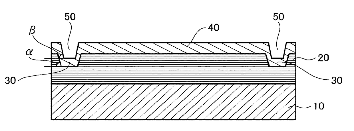
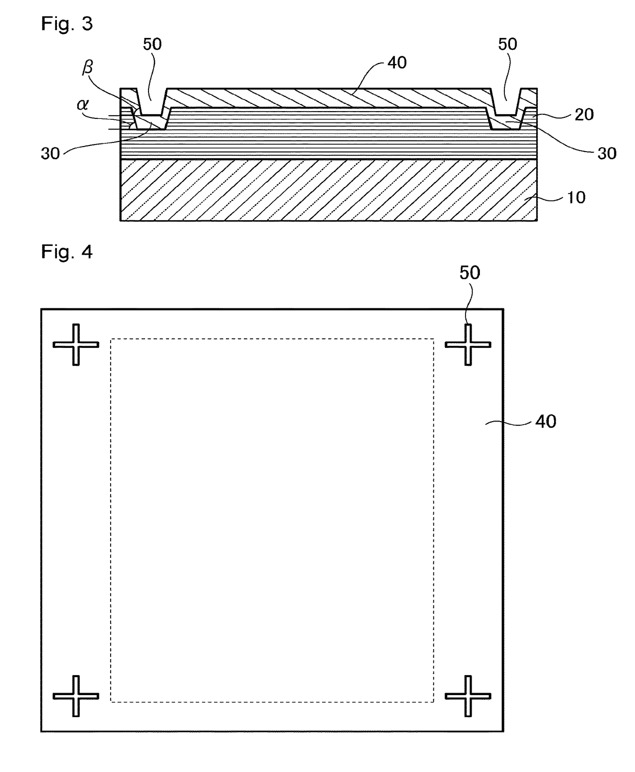
[0140]In this Example, a reflective mask blank as shown in FIGS. 3 and 4 are produced.

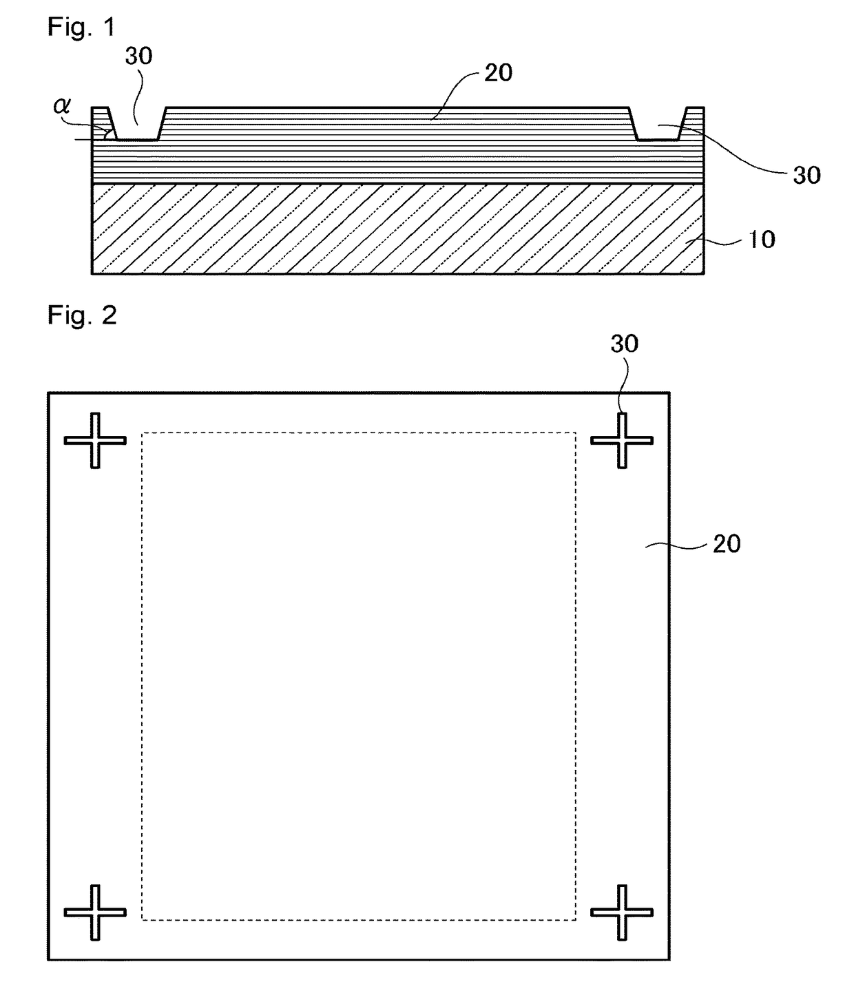
[0141]As the substrate for film deposition 10, a SiO2—TiO2 based glass substrate (having outer dimensions of 6 inch, i.e. 152.4 mm square and a thickness of 6.3 mm) is used. The glass substrate has a thermal expansion coefficient of 0.2×10⁻⁷ / ° C., a Young's modulus of 67 GPa, a Poisson ratio of 0.17 and a specific rigidity of 3.07×10⁷ m2 / s2. The glass substrate is polished to have a smooth surface with at most 0.15 nm in Rq and have a flatness of at most 100 nm.

[0142]The substrate 10 has a high dielectric coating a sheet resistance of 100 Ω / square (not shown) applied on the back side by depositing a Cr film having a thickness of 100 nm by use of a magnetron sputtering method.

[0143]The Cr film formed by the above-mentioned procedure is used to fix the substrate 10 (having outer dimensions of 6 inch, i.e. 152.4 mm square and a thickness of 6.3 mm) to an ordinary planar electrostatic chuck, and Mo fil...

example 2

[0162]The same procedure as Example 1 is carried out except that the inclination angle α of the concave portion forming each of the fiducial marks 30 formed on the front side of a reflective multilayer film 20 by use of the FIB method is 32°, that the concave portion has a depth of 80 nm, and, that the input power among the conditions in deposition of a TaN layer as the absorber layer is a half (½ P) of the one (P) in Example 1. The inclination angle β of the concave portion forming each of the transferred marks 50 is 63°, and the concave portion has a depth of 80 nm. The difference between the inclination angle β of the concave portion forming each of the transferred marks 50 and the inclination angle α of the concave portion forming each of the corresponding fiducial marks 30 (inclination angle β−inclination angle α) is 31°.

example 3

[0163]The same procedure as Example 1 is carried out except that the inclination angle α of the concave portion forming each of the fiducial marks 30 formed on the front side of a reflective multilayer film by use of the FIB method is 31°, that the concave portion has a depth of 81 nm, and that the input power in the conditions for deposition of a TaN as the absorber layer 40 is ¼ (¼ P) of the one (P) in Example 1. The inclination angle β of the concave portion forming each of the transferred marks 50 is 55°, and the concave portion has a depth of 81 nm. The difference between the inclination angle β of the concave portion forming each of the transferred mark 50 and the inclination angle α of the concave portion forming each of the corresponding fiducial marks 30 (inclination angle β−inclination angle α) is 24°.


PUM

PropertyMeasurementUnit
thicknessaaaaaaaaaa
inclination angleaaaaaaaaaa

Abstract

A reflective mask blank, which includes a substrate, a reflective multilayer film for reflecting exposure light, and an absorber layer for absorbing the exposure light in this order; the reflective multilayer film having at least three fiducial marks formed in a concave shape in an area outside an exposure area for patterning the reflective multilayer film on a front side thereof, each of the fiducial marks including a concave portion having an inclination angle α, the absorber layer having a film thickness of from 40 to 90 nm; the absorber layer having transferred marks formed in a concave shape on a front side thereof, the transferred marks being transferred from the at least three fiducial marks, each of the transferred marks including a concave portion having an inclination angle of from 35 to 80°; and a difference between the inclination angle β and the inclination angle α (inclination angle β−inclination angle α) being at least 10°.

Description

FIELD OF INVENTION[0001]The present invention relates to a reflective mask blank and a process for producing a reflective mask blank.BACKGROUND OF INVENTION[0002]Recently, in order to make it possible to transfer micropatterns having a size of 40 nm or less, EUV exposure technology has been promising in place of the existing ArF exposure technology that uses ArF excimer laser light having a wavelength of 193 nm. The EUV exposure technology uses, as the exposure light, EUV (Extreme Ultra-Violet) light having a shorter wavelength than the ArF excimer laser light. The EUV light includes a soft X-ray and vacuum UV light, and is specifically light having a wavelength of from about 0.2 to 100 nm. At present, as the exposure light, EUV light having a wavelength of about 13.5 nm is mainly investigated.[0003]In the EUV lithography (EUVL) technology, a reflective photomask is used. The reflective photomask includes a multilayer reflective film and an absorber layer formed in this order on a s...

Claims


Application Information

Patent Timeline
Patent Type & Authority Patents(United States)
IPC IPC(8): G03F1/24
CPCG03F1/24G03F1/42
Inventor HANEKAWA, HIROSHIKAGEYAMA, JUNICHIHAYASHI, KAZUYUKI
Owner ASAHI GLASS CO LTD
Why Eureka
Try Eureka