Imaging system for processing a media

a technology of imaging system and media, applied in the direction of adaptive control, electric controller, instruments, etc., can solve the problems of degrading image quality, increasing the complexity and cost of the known imaging system, and increasing the difficulty in meeting the strict positioning tolerance, etc., to achieve precise stepping and high quality printing

Active Publication Date: 2018-03-27
OCE TECH
View PDF14 Cites 3 Cited by
  • Summary
  • Abstract
  • Description
  • Claims
  • Application Information

AI Technical Summary

Benefits of technology

[0062]The actuation command u, which may for example be an input voltage V for driving the electric medium roll motor 4, comprises a feedback and feedforward component ufb, uff. The status parameters θ1, θ2, θ3 are applied by the processor 11 for determining the feedforward component uff. In FIG. 3, the position setpoint Sp, which for example is the desired angular position of the medium roller 2, is input to the processor 11 to derive an actuation command estimate uff by means of a feedforward algorithm 11b. From the position setpoint Sp the processor 11 determines one or more setpoint parameters d / dt, d2 / dt2, d3 / dt3, such as the time derivatives d / dt, d2 / dt2, d3 / dt3. Any number or order of time derivatives may be applied. The processor 11 combines setpoint parameters d / dt, d2 / dt2, d3 / dt3 with the status parameters θ1, θ2, θ3 to obtain an accurate estimate 0 of the actuation command u. By utilizing in the feedforward algorithm 11a the status parameters θ1, θ2, θ3 determined by the algorithm 11a, the feedforward algorithm 11b uses a continuously up-to-date input, such that the estimate û takes into account the decreasing inertia and outer radius of the medium roll 3a as it unspools. As such, the feedforward algorithm 11b provides an accurate estimate û of the command estimate u, which allows for precise stepping and high quality printing.

Problems solved by technology

Any deviation of the position of the print media relative to the printing station may result in a degraded image quality, as a result of misplacement of particles of marking material on the print media.
In general, due to the stricter positioning requirements, it becomes increasingly more difficult to satisfy the strict positioning tolerances.
In general, this leads to an increasingly more complex and expensive construction of the known imaging systems.
In practice, it has been found that, especially during continued operation, the accuracy of the positioning of the print media relative to the printing station in the above mentioned imaging system is insufficient to obtain high quality printing.
A drawback of U.S. Application Publication No. 2011 / 0211031A1 is that the medium positioning is secondary to its speed, resulting in incorrectly overlapping bands of the printed image, when printing in consecutive swaths.
These positioning artifacts are often directly visible to the user and reduce the image quality.
A further drawback is that during long time operation, the accuracy of the method in U.S. Application Publication No. 2011 / 0211031A1 is reduced, since the feedback mechanism is arranged to correct for incidental changes, but not for long term gradual changes in the system.
This makes U.S. Application No. 2011 / 0211031 A1 and U.S. Application Publication No. 2015 / 0166289 A1 less suitable for high quality prints applied in the graphic arts industry.

Method used


Image

  • Imaging system for processing a media
  • Imaging system for processing a media
  • Imaging system for processing a media

Examples


example 1

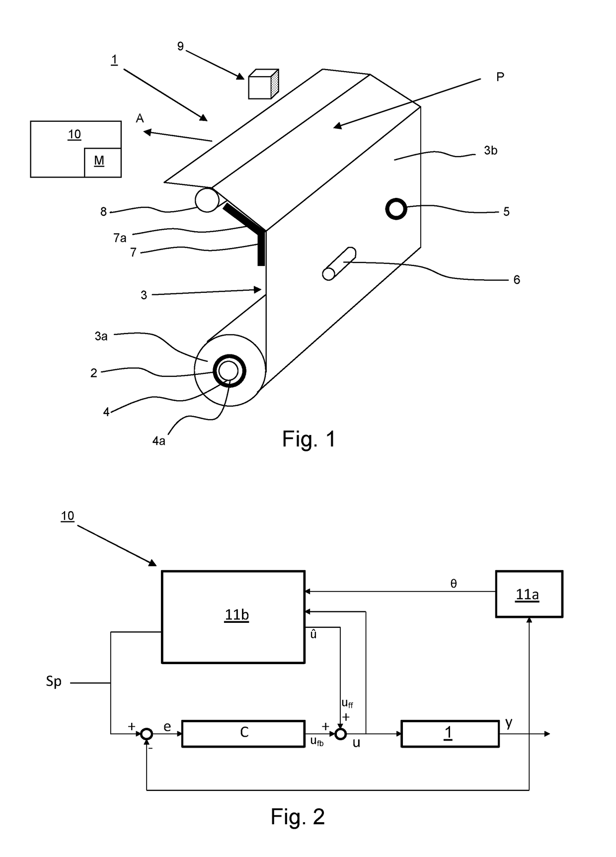
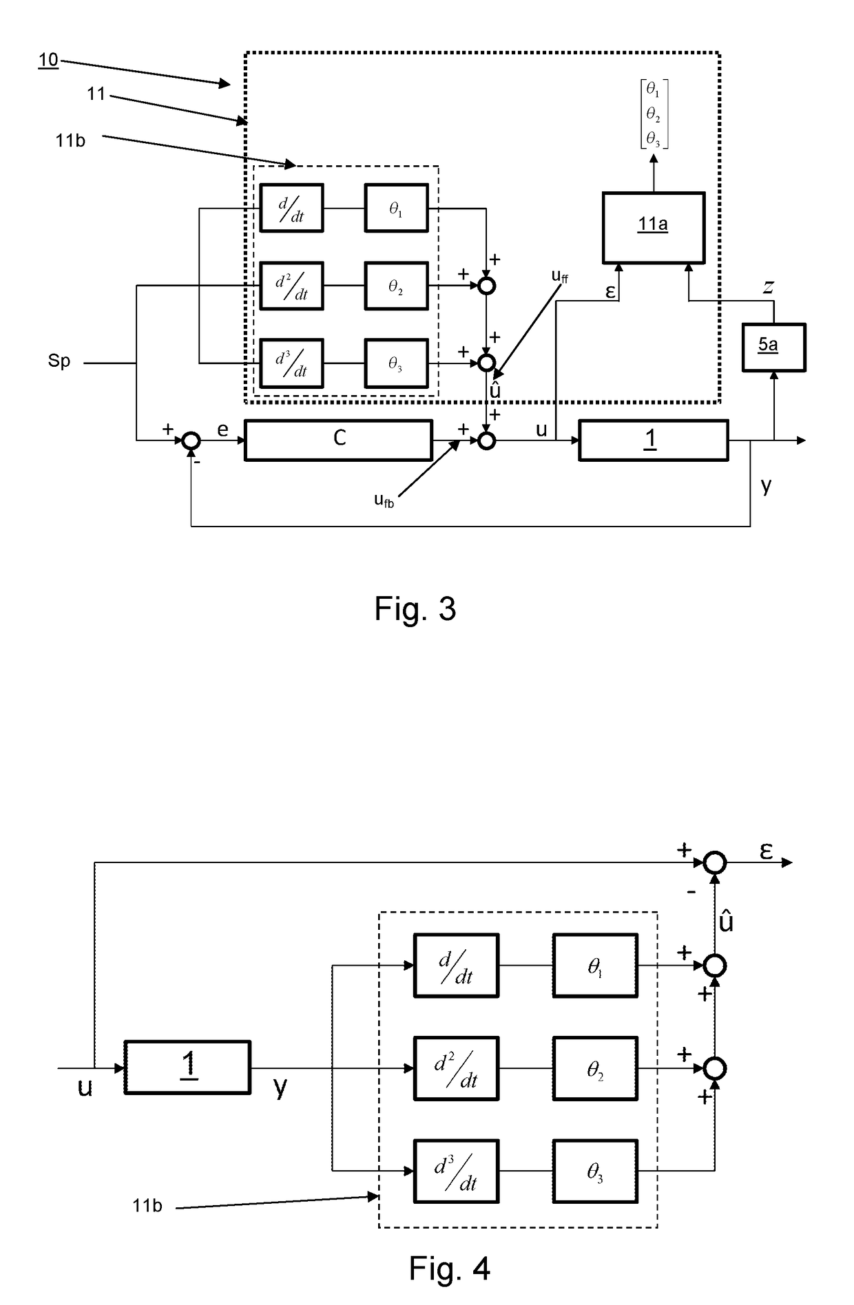
[0063]The controller assembly 10 in FIG. 3 further comprises a feedforward controller 11b, which may be either a hardware or software-based controller. The position setpoint Sp is applied as input for determining the feedforward component uff output by the feedforward controller 11b. From the position setpoint Sp, one or more time derivatives are derived as indicated by the blocks d / dt, d2 / dt2, d3 / dt3 in FIG. 3. Each block d / dt, d2 / dt2, d3 / dt3 corresponds to an order of the time derivative of the position setpoint Sp, i.e. d / dt is the first order time derivative of the position setpoint Sp, d2 / dt2 is the second order time derivative of the position setpoint Sp, etc. By converting the position setpoint Sp into a plurality of time derivative signals d / dt, d2 / dt2, d3 / dt3, the dynamics of the system 1 may be identified. The time derivatives d / dt, d2 / dt2, d3 / dt3 are combined with the status parameters θ1, θ2, θ3 to determine an actuation command estimate û. Preferably, a status parameter...

example 2

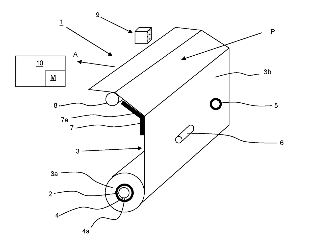
[0083]In FIG. 5, an imaging system 100 according to the present invention is illustrated as a block diagram. The imaging system 100 comprises a feedback controller assembly C′ and a feedforward controller with a feedforward algorithm 11b similar to those described with respect to FIGS. 1-3. The position signal y generated by the sensor device 5 is used as the basis for a feedback or a feedforward signal ufb, uff. FIG. 5 illustrates the different components of the position signal y, namely the angular signal y1 representing the angular position of the actuator 4, the tension signal y2 representing the tension in medium 3b, and the advancement signal y3 corresponding to the position of the medium 3. The position signal y3 may be generated by the encoder wheel 5, the tension signal y2 by means of the tension encoder 7a in the buffer 7, while the roll-motor encoder 4a may be applied for obtaining the advancement signal y1.

[0084]FIG. 5 shows that the observer 5a determines the medium rol...


PUM


Abstract

An imaging system includes an imaging station, an actuator for driving a medium roller for controllably displacing the medium along a media transport path, and a controller assembly. The controller assembly includes a sensor device for generating a position signal and a processor for processing the position signal. The actuator is actuated in response to an actuation command from the controller assembly, which actuation command is derivable from a feedback component and a feedforward component. The feedback component is based on a position error. The processor is further arranged for determining a time dependent status parameter, which status parameter represents a status of the medium on the medium roller. The processor is further arranged for deriving an actuation command estimate based on the status parameter, and wherein the feedforward component includes the actuation command estimate.

Description

CROSS-REFERENCE TO RELATED APPLICATIONS[0001]This application claims priority under 35 U.S.C. § 119(a) to Application Nos. 15179952.5 and 15198422.6, filed in Europe on Aug. 6, 2015 and Dec. 8, 2015, respectively. The entire contents of each of the above-identified applications are hereby incorporated by reference into the present application.BACKGROUND OF THE PRESENT INVENTION[0002]1. Field of the Invention[0003]The present invention relates to an imaging system for processing a media, comprising a media transport path, an imaging station arranged along said media transport path, a displacement device configured to controllably displace the media along the media transport path relative to said imaging station, and a controller assembly.[0004]2. Description of Background Art[0005]In known imaging systems, the media is positioned relative to the imaging station by means of commonly known transport pinches, which are driven by electric motors. The increasing demands for higher image q...

Claims


Application Information

Patent Timeline
Patent Type & Authority Patents(United States)
IPC IPC(8): G06K15/00B41J15/04H04N1/00G05B11/42G05B13/04
CPCG06K15/4065B41J15/04G05B11/42G05B13/04H04N1/00702H04N1/00732H04N1/00734H04N1/00779G06K15/408B65H2557/262B65H23/048B65H23/1825B65H23/185B65H23/28B65H2404/612B65H2553/51B65H2801/36B65H2515/31B65H2220/01
Inventor WINTERAEKEN, STEFAN A. C. J.BOONEN, RIK W. J.
Owner OCE TECH
Why Eureka
Try Eureka