Method for identifying objects in a subject's ear

a technology of objects and eardrums, applied in the field of objects identifying in the ears of subjects, can solve the problems of misinterpretation of the status of the inner ear canal or the eardrum, physicians often fail to determine the status of e.g. the eardrum or the eardrum, and only well trained physicians are currently subject to the otoscope of the ar

Inactive Publication Date: 2018-04-03
HELEN OF TROY LTD
View PDF112 Cites 4 Cited by
  • Summary
  • Abstract
  • Description
  • Claims
  • Application Information

AI Technical Summary

Benefits of technology

[0025]In particular, in many cases, the ear canal of the outer ear is not straight-lined, but exhibits at least one curvature, especially at a transition area or transition point between soft connective tissue and hard bone confining the ear canal. The “corner” is provided by this curvature. Consequently, when carrying out the method of the present invention, the requirement to deform the subject's ear is eliminated or greatly reduced. Furthermore, the inventive method avoids the risk of injury to the ear canal, in particular the bony part of the ear canal, or to the eardrum by allowing the use of otoscopes with a tip of the head portion that exhibit significantly larger dimensions as compared to an otoscope according to the art. Thus, the risk of introducing the head portion of the otoscope too deeply into the subject's ear canal is considerably reduced. Both improvements pave the way to allow laypersons to carry out the method according to the invention.
[0178]Preferably, the otoscope further comprises an infrared sensor unit positioned at the distal end of the head portion, especially centrically at the distal tip. Providing an otoscope comprising an infrared sensor unit for temperature detection in conjunction with an optical identification of objects allows for more reliable identification of the objects, e.g. of the eardrum.

Problems solved by technology

For the above reasons, reliably and securely handling an otoscope of the art is currently subject to only well trained physicians and not amenable to the larger community of practitioners.
A study recently published in the US as a result of a survey has shown that even physicians often fail to (correctly) determine the status of e.g. the subject's eardrum or fail to correctly interpret the image provided by the otoscope (i.e. correct and meaningful object recognition).
Such failures result in misinterpretation of the status of the inner ear canal or the eardrum.
As a consequence, e.g. over-medication with antibiotics for treating supposed inflammations of the eardrum occurs, because physicians tend to err on the side of caution, or meaningless image interpretation occurs.
In order to obtain images having a satisfying resolution, a significant number of individual light guides must be provided rendering devices by far too expensive for routine care.
For the above reasons, they are not configured and suitable for domestic use by a larger community of practitioners, nor use by laypersons.
As a result of these common characteristics, ease of use (due to safety issues) is limited for such devices.
Methods for reliable detection of objects in the ear canal, including the eardrum, are remarkably intricate with such known otoscopes.
Furthermore, illumination at different angles may drastically change the reflective pattern and appearance of objects which are arranged close to the electronic imaging unit, while the reflective pattern and appearance of more distant objects only varies slightly.
Under such circumstances, any object in the ear canal, e.g. a hair, which—at least partially—obstructs the view of the electronic imaging unit at a certain position within the ear canal onto the eardrum, may not prevent the user from obtaining the desired image information.
For example, it may be impossible for the electronic imaging unit to detect the eardrum and / or the inner part of the ear canal—irrespective of the position of the electronic imaging unit within the ear canal—because the ear canal is blocked by massive earwax or other particles.
Alternatively, the eardrum may not be identified because the user did not carry out the inventive method due to inappropriate handling of the corresponding device (otoscope).
When introducing the tip end of the head portion no deeper into the ear canal than to the border between the outer part and the inner part of the outer ear canal of the subject's outer ear, i.e. to a transition area between the two types of tissue, there is the risk that artifacts, such as earwax, hair and other kind of dirt from the outer part of the outer ear canal obstruct the view of the small electronic imaging unit onto the subject's eardrum.
Particularly, the second curvature of the ear canal obstructs any optical line of sight or visual communication of an otoscope which is not introduced as far as at least some millimeters within the bony part of the ear canal.
But, this kind of “alignment” of the otoscope or this kind of straightening out the ear canal is painful.
Injuring the inner part of the ear canal even bears the risk of cardiovascular complications through vagal overstimulation.
Furthermore, the longitudinal force upon introduction into the ear canal can be limited by a telescoping mechanism or the use of an elastic element.
Therefore, if the user (untrained) does not pay attention, the tip portion might be introduced deeply into the inner part of the outer ear canal causing serious injuries to the subject.
Thus, for an optical axis being arranged with a high radial offset, i.e. close to an inner lateral surface of the ear canal, there may be an increased likelihood of earwax particles adhering to the probe cover at a section covering the optical axis, thereby obstructing the view onto the eardrum.
This, however, would interfere with object identification (e.g. if the object to be identified is the eardrum) and elimination of artifacts from the captured images.
However, artifacts that are relatively close to the electronic imaging unit (such as hair and earwax) will change their appearance (position) drastically.

Method used


Image

  • Method for identifying objects in a subject's ear
  • Method for identifying objects in a subject's ear
  • Method for identifying objects in a subject's ear

Examples


Embodiment Construction

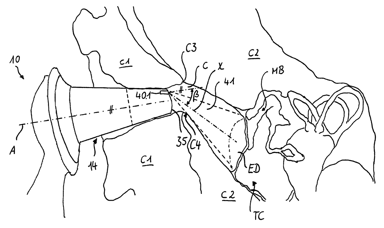
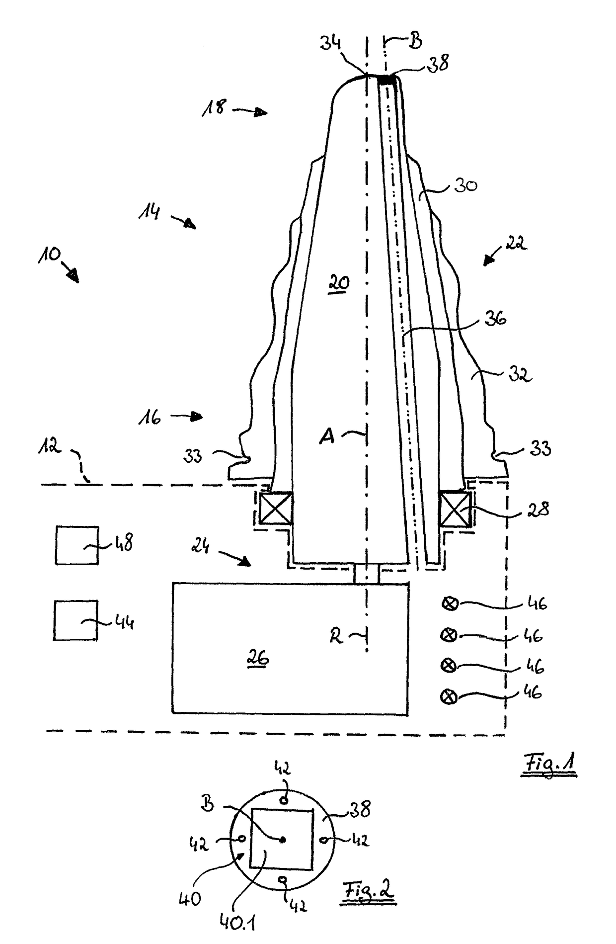
[0200]FIG. 1 schematically shows a cross-sectional view of a head portion 14 and a part of a handle portion 12 (only shown in phantom lines) of an embodiment of an otoscope 10 adapted for carrying out the method according to the present invention. As can be seen from FIG. 1, the head portion 14 has a substantially tapering form extending along a longitudinal axis A of the head portion 14. The head portion 14 comprises a relatively large proximal end 16 adjacent to the handle portion 12 and a smaller distal end 18. The distal end 18 of the head portion 14 is adapted to be introduced into a subject's ear canal.

[0201]Furthermore, the head portion 14 comprises a rotatable, radial inner portion 20 and a fixed, radial exterior portion 22. The rotatable portion 20 is rotatable about an axis of rotation R which—in the shown exemplary embodiment—corresponds to the longitudinal axis A of the head portion 14. A motion mechanism 24 comprising a servo motor 26 is positioned within the handle por...


PUM


Abstract

A method of identifying objects in a subject's ear, comprising the following steps: introducing an optical electronic imaging unit and a light source into an ear canal of a subject's outer ear, wherein the electronic imaging unit exhibits an optical axis directed in a distal direction, especially directed at the eardrum of the subject's ear; using the electronic imaging unit to capture an image from an eccentric observation point positioned on the optical axis and positioned eccentrically within the ear canal; and determining brightness or color information to identify objects shown in the image by electronic means, in order to automatically identify the objects, especially the eardrum.

Description

FIELD OF THE INVENTION[0001]The invention refers to a method of identifying objects in a subject's ear. Looking into ears is called “otoscopy”. Otoscopy is a standard medical examination technique established more than 100 years ago. Medical students learn otoscopy early in their studies during the practical course in physiology. Otoscopic examination assists the skilled physician in examining the ear canal or eardrum which may be affected e.g. by otitis media (OM), otitis media with effusion (OME), otitis externa, and eardrum perforation. OME is defined by the presence of middle ear effusion, i.e. a liquid behind an intact tympanic membrane without signs or symptoms of acute infection. OME is one of the most frequent pediatric diagnoses. Object recognition in otoscopy is also directed to the identification of particles or any material, e.g. hair, earwax, foreign objects, etc., which may obstruct the ear canal or coat the eardrum. Such applications are highly desired for routine car...

Claims


Application Information

Patent Timeline
Patent Type & Authority Patents(United States)
IPC IPC(8): A61B1/267A61B1/07A61B5/00A61B1/227A61B5/11A61B1/05A61B5/107A61B1/06A61B5/01A61B1/00
CPCA61B1/00142A61B1/00057A61B1/00066A61B1/00101A61B1/00179A61B1/05A61B1/051A61B1/0623A61B1/0638A61B1/0676A61B1/0684A61B1/07A61B1/227A61B1/2275A61B5/0075A61B5/0086A61B5/01A61B5/1077A61B5/11A61B5/6817A61B5/7203A61B5/7221A61B5/7246A61B5/7264A61B5/7275A61B5/74A61B1/00009A61B2562/0242A61B1/00193A61B5/065A61B5/6885A61B5/6886A61B1/000094
Inventor RUPPERSBERG, PETERLEPPLE-WIENHUES, ALBRECHT
Owner HELEN OF TROY LTD
Why Eureka
Try Eureka