Method and apparatus for extrusion processing of high fiber content foods

a technology of high fiber content and extruder, which is applied in the direction of feeding-stuffs, transportation and packaging, rotary stirring mixers, etc., can solve the problems of inability to meet end users, difficult to extrude at commercially useful rates, and weak structural properties of feeds, etc., to achieve low specific mechanical energy (sme) inputs and high levels of specific thermal energy

Inactive Publication Date: 2018-04-03
WENGER MANUFACTURING INC
View PDF19 Cites 4 Cited by
  • Summary
  • Abstract
  • Description
  • Claims
  • Application Information

AI Technical Summary

Benefits of technology

[0010]A feature of the present invention is that the extrusion equipment is designed to process comestible feed ingredients using relatively high levels of specific thermal energy (STE) derived steam / water injection, with lower specific mechanical energy (SME) inputs, as compared with conventional equipment. To this end, the extrusion screw assembly within the extruder barrel is designed to alternately convey and work the feed ingredients while permitting injection of significant amounts of steam into the barrel. Thus, the extruder provides alternating zones of steam injection with zones of high friction and shear so that the material is fully hydrated and cooked. At the same time, operation of the extruder does not require very high horsepower, and does not result in undue wear on the extruder parts.

Problems solved by technology

However, these fibrous ingredients when used at levels above about 20% by weight, can be difficult to extrude at commercially useful rates.
If this equipment is operated at normal production rates, the resultant feeds are structurally weak and tend to crumble, and are not acceptable to end users.
Accordingly, it has heretofore not been practical to use high levels of fibrous ingredients in aqua feeds, notwithstanding the potential cost savings which could be realized with such feed formulas.

Method used


Image

  • Method and apparatus for extrusion processing of high fiber content foods
  • Method and apparatus for extrusion processing of high fiber content foods
  • Method and apparatus for extrusion processing of high fiber content foods

Examples


Embodiment Construction

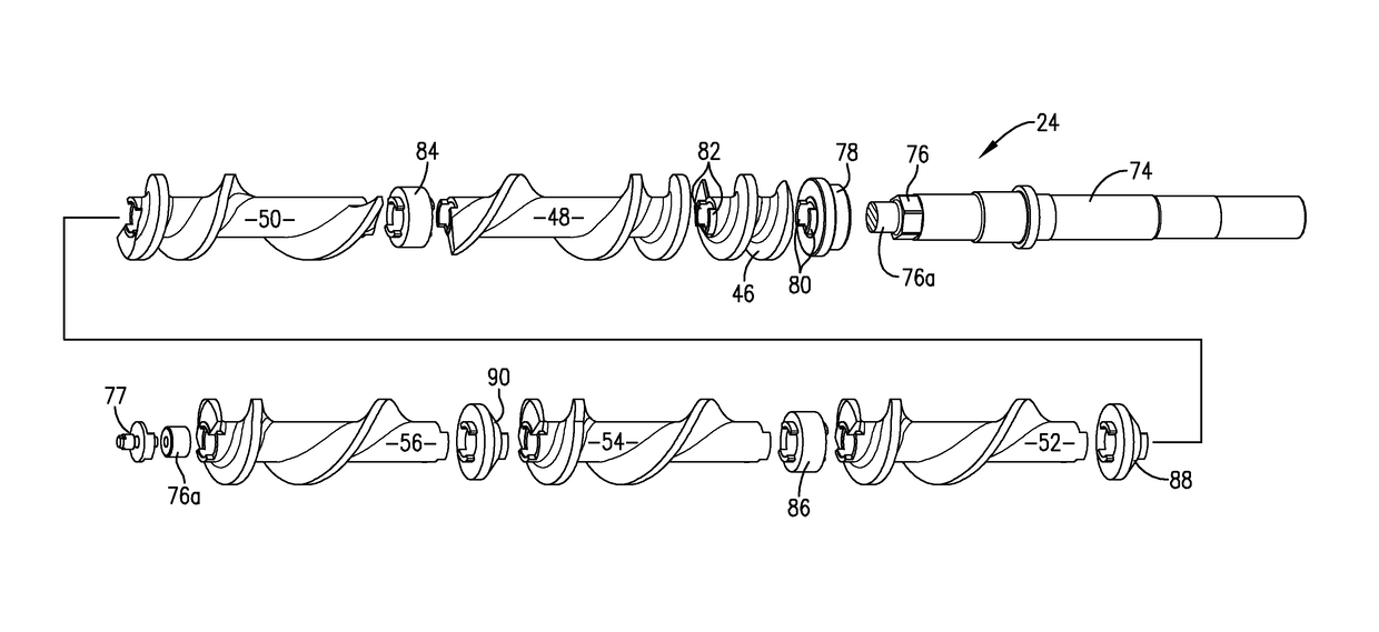
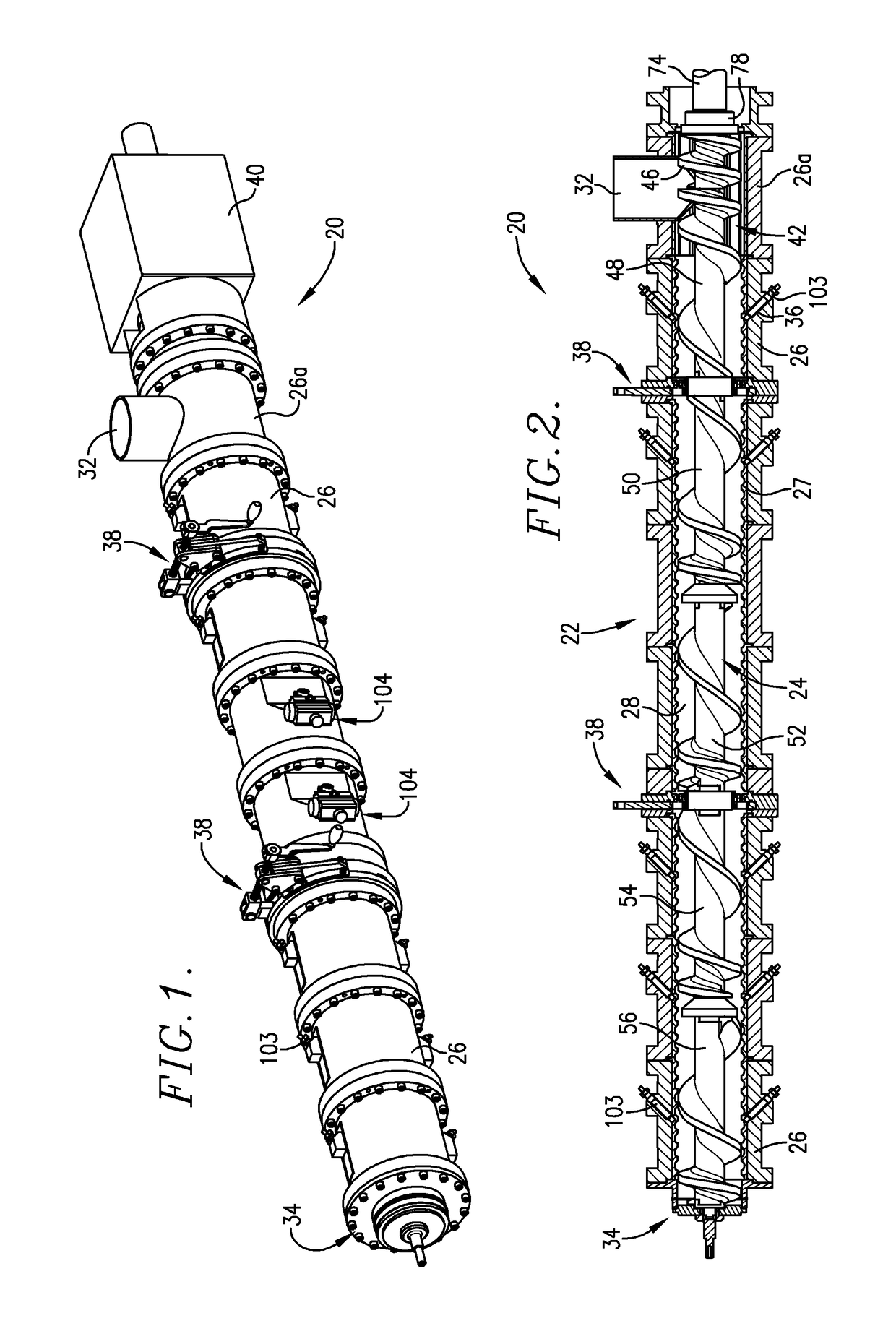
[0021]Turning now to the drawings, a single screw extruder 20 is illustrated in FIGS. 1 and 2, and generally includes an elongated barrel 22 with an elongated, axially rotatable screw 24 situated within the barrel 22. The barrel 22 has a plurality of tubular sections or heads 26, including an inlet head 26a, bolted together in an end-to-end relationship to present an internal bore 28 extending the full length of the barrel. In the depicted embodiment, each of the heads 26 save for inlet head 26a is equipped with an inner, helically ribbed sleeve 27.

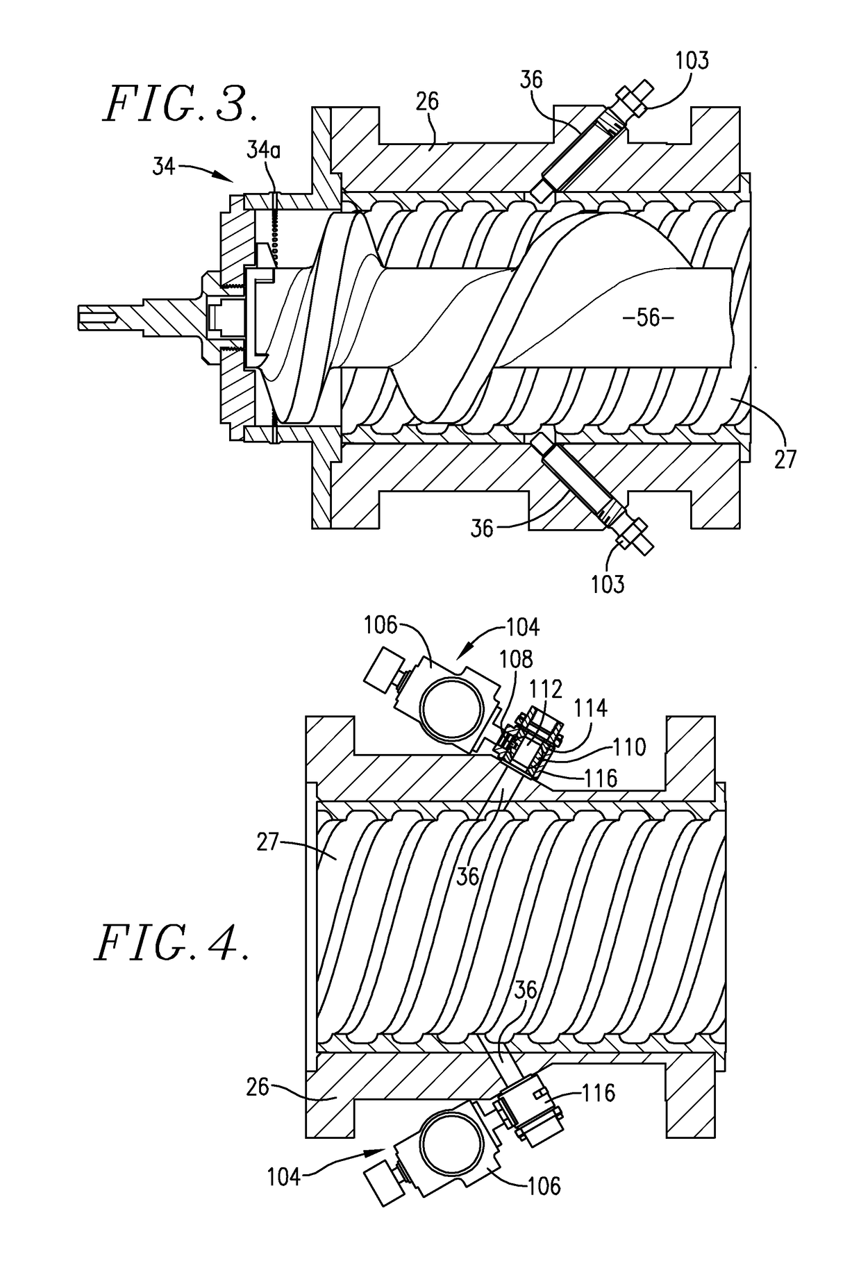
[0022]The inlet head 26a includes an upright, tubular material inlet 32 for feeding material into the barrel 22 for processing. The opposite end of the barrel 22 is equipped with a die assembly 34 presenting restrictive orifice outlets 34a for the material being processed (see FIG. 3). The barrel 22 is also equipped with a series of obliquely oriented steam injection ports 36 along the length thereof, together with a pair of manually oper...


PUM

PropertyMeasurementUnit
free volume V4aaaaaaaaaa

Abstract

An extruder (20) is specifically designed for the production of animal feed products (e.g., aquatic feeds) containing substantial quantities of low-cost fibrous materials, such as rice byproducts, at high production rates. The extruder (20) includes an elongated barrel (22) with a screw assembly (24) within the barrel and an endmost extrusion die assembly (34). The screw assembly (24) includes an inlet screw assembly (42) and a processing screw assembly (44). The assembly (44) includes screw components (50-56) of differential pitch to present a long pitch inlet section (64) and a tight pitch discharge section (68). Materials passing through the screw assembly (24) are successively subjected to high levels of steam injection (STE) followed by high levels of friction and shear (SME), so that the STE / SME ratio is at least about 6 / 1.

Description

BACKGROUND OF THE INVENTION[0001]Field of the Invention[0002]The present invention is broadly concerned with improved extruders and screw configurations designed for the economical production of animal feed products containing high quantities of fibrous ingredients. More particularly, it is concerned with such extrusion equipment which is capable of processing feed products, e.g., aquatic feeds, containing in excess of 20% by weight of fibrous ingredients at commercially acceptable production rates.[0003]Description of the Prior Art[0004]The aquaculture industry commonly makes use of extruded feed products having various nutritional profiles and operational characteristics, such as sink rates. For example, an acceptable salmon feed would have very different properties as compared with a shrimp feed. Accordingly, in the production of these feeds, the ingredients must be carefully selected and processed so as to achieve the optimal feed for a particular aquatic creature.[0005]Many aqu...

Claims


Application Information

Patent Timeline
Patent Type & Authority Patents(United States)
IPC IPC(8): B01F7/08A23K10/37A23K50/80A23K40/20A23K40/25B29C47/60B29C47/62B29C47/38A23N17/00B29C48/395B29C48/59
CPCB01F7/086A23K10/37A23K40/20A23K40/25A23N17/005B29C47/6025B29C47/6075A23K50/80Y02P60/877B01F2215/0008B29C48/59B29C48/535Y02P60/87B01F27/724B01F2101/18
Inventor WENGER, MARC
Owner WENGER MANUFACTURING INC
Why Eureka
Try Eureka