Metal plate joining method and apparatus

a metal plate and jointing technology, applied in non-electric welding apparatus, welding/cutting auxillary devices, auxillary welding devices, etc., can solve the problems of increasing the method cannot roll the joint portion to a level corresponding to the thickness of the base material, etc., to reduce the increase of the thickness of the joint portion, reduce the step gradient, and smooth the step

Active Publication Date: 2018-04-03
PRIMETALS TECHNOLOGIES JAPAN LTD
View PDF86 Cites 5 Cited by
  • Summary
  • Abstract
  • Description
  • Claims
  • Application Information

AI Technical Summary

Benefits of technology

[0030]According to the present invention, the respective axes of the pair of upper and lower pressure rollers are tilted in the horizontal plane with respect to the straight line perpendicular to the joint line, and then the pair of pressure rollers is positively driven to thereby roll the step defined at the joint portion after welding. Therefore, the shear deformation in the direction perpendicular to the joining line can reduce the increased amount of thickness of the joint portion, smooth the step and reduce the step gradient. Thus, a high degree of joint strength can be ensured.
[0031]According to the present invention, the step defined at the joint portion of the metal plates is smoothed and the step gradient can be reduced. Therefore, the stress concentration factor of the joint portion can be reduced to ensure a high degree of joint strength. Thus, the following effects can be produced. The application range of the mash seam welding can be increased. It is possible to prevent a work roll on a steel product line from being scratched. Productivity and yield can be improved.
[0032]That is, in the present invention, the step defined at the joint portion subjected to the mash seam welding can be smoothed. Therefore, in a cold rolling process for steel production, the work roll can be prevented from being scratched during the cold rolling as the next process and anti-tension performance can be improved. Thus, the mash seam welding can be applied to the cold rolling process to which the mash seam welding has not heretofore been applied.
[0033]Also in tailored blanks, because of stress concentration on the step defined at the joint portion, the application of the mash seam welding to a portion requiring fatigue strength has been avoided. However, because of the smoothed step, the stress concentration is alleviated and press formability is improved. Therefore, an expensive laser beam welder can be replaced with the inexpensive mash seam welder.
[0034]In a continuous annealing line and in a production line including galvanized sheet iron manufacturing facilities or the like, the contact angle (stress concentration factor) between each of the work rolls of a skin pass rolling mill and the joint portion can be reduced. Consequently, the contact surface pressure between the work roll and the material can be reduced. It is possible, therefore, to prevent the scratching of the work roll and the mark transfer of the joint portion without lowering a line speed. Thus, productivity and yield can be improved.
[0035]Also in the case where the metal plates having different thicknesses are joined to each other by laser beam welding, flash butt welding or friction stir welding, similarly the shear deformation can smooth the steps and reduce the step gradient. Therefore, the following effects can be produced. The laser beam welding, flash butt welding and friction stir welding can each widely be applied to a cold rolling process or tailored blanks to which they have not been applied. It is possible to prevent a work roll on a steel product line from being scratched. Productivity and yield can be improved.

Problems solved by technology

However, this welding method cannot roll the joint portion to a level corresponding to the base material thickness.
There is a problem in that the thickness of the joint portion is increased to approximately 120% to 160% of the thickness of the base material (the metal plate), which forms a step between the joint portion and the base material.

Method used


Image

  • Metal plate joining method and apparatus
  • Metal plate joining method and apparatus
  • Metal plate joining method and apparatus

Examples


Embodiment Construction

[0107]Embodiments of the present invention will hereinafter be described with reference to the drawings. A metal plate of the embodiments is described taking a cold rolling for steel product plant as an example.

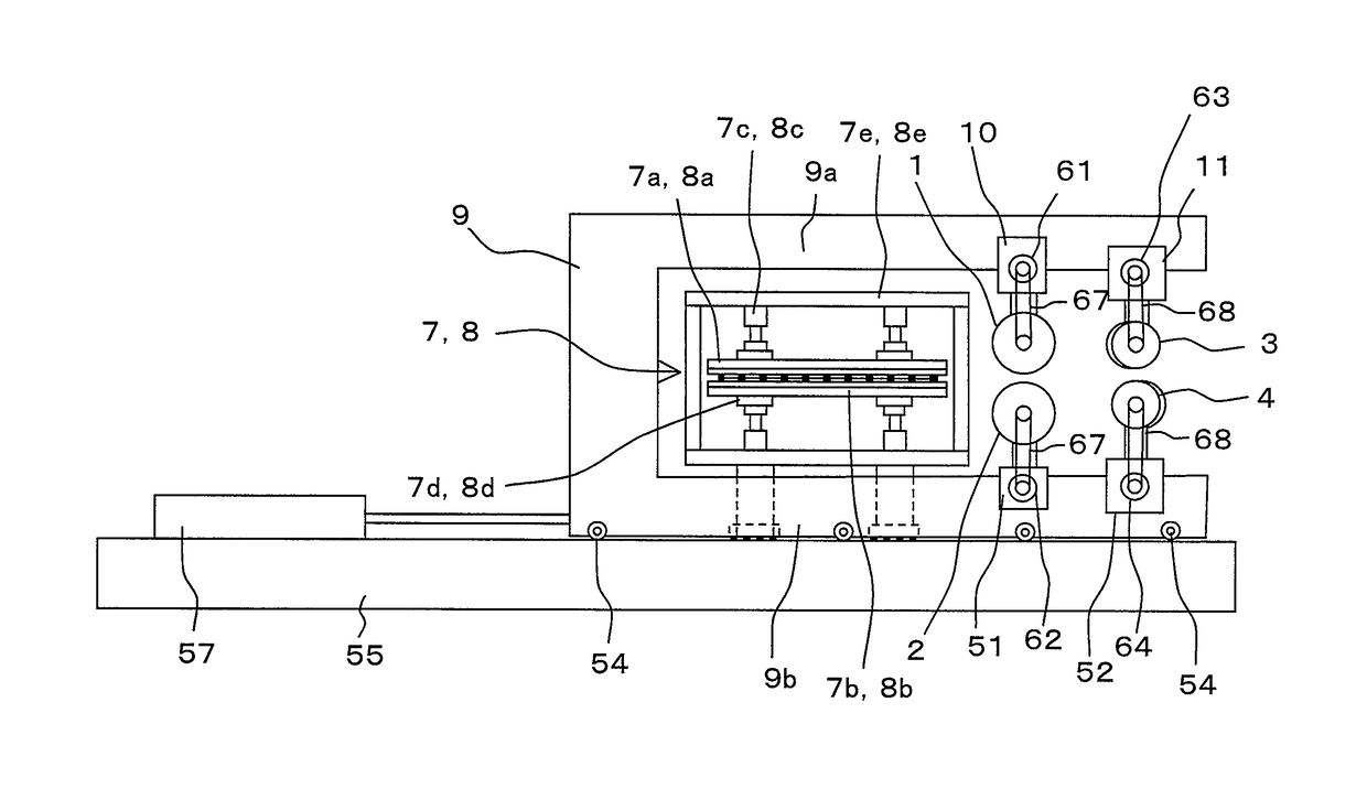
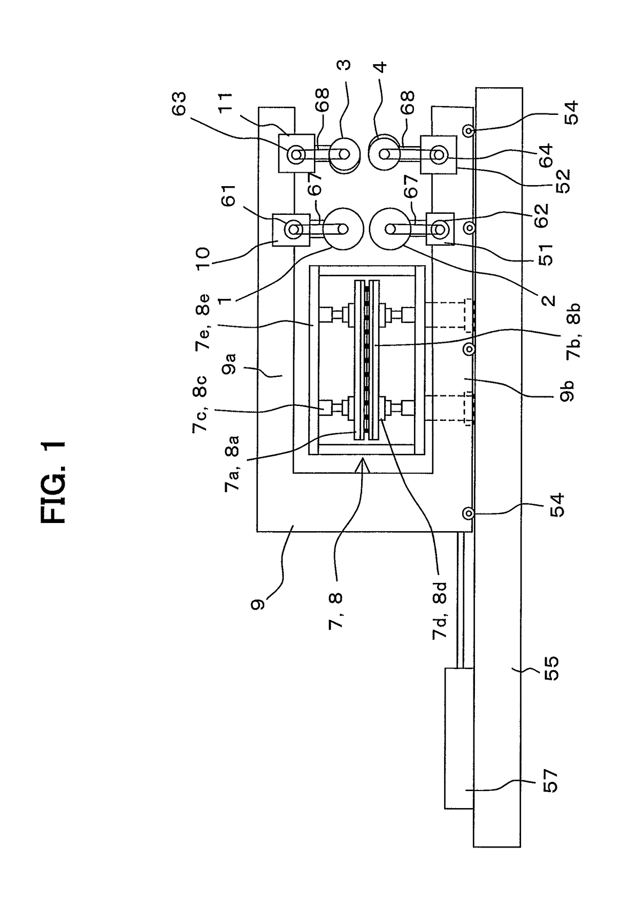
[0108]FIG. 1 is a schematic view of a metal plate joining apparatus according to an embodiment of the present invention. The present embodiment corresponds to the case where the present invention is applied to a mash seam welder.

[0109]Referring to FIG. 1, a metal plate joining apparatus according to the embodiment includes a pair of upper and lower electrode wheels 1, 2, a pair of upper and lower pressure rollers 3, 4, entry side and delivery side clamp devices 7, 8, a carriage frame 9, an electrode wheel pressing device 10, and a pressure roller pressing device 11. The electrode wheel pressing device 10 and the pressure roller pressing device 11 are hydraulic cylinders, for example. The upper electrode wheel 1 and the upper pressure roller 3 are supported by an upper horizon...


PUM

PropertyMeasurementUnit
temperatureaaaaaaaaaa
temperaturesaaaaaaaaaa

Abstract

A pair of upper and lower pressure rollers 3, 4 is disposed so that their axes 15, 16 are tilted in a horizontal plane in respective directions opposite to each other with respect to a straight line perpendicular to a welding line of a joint portion J. The pressure rollers 3, 4 are positively driven by corresponding electric motors 63, 64 to thereby roll the joint portion. Thus, steps defined at the joint portion can be smoothed and a step gradient can be reduced to ensure a high degree of joint strength. Thus, it is possible to prevent a step portion from being interfolded into the base material of the meal plates 5, 6.

Description

TECHNICAL FIELD[0001]The present invention relates to a metal plate joining method and apparatus that can smooth a step defined at a joint portion of two metal plates and reduce a step gradient of the joint portion.BACKGROUND ART[0002]A mash seam welder employs a welding method as below. Two metal plates are placed to overlap each other at their end portions. The overlapping portions are pressed by a pair of electrode wheels and continuously welded together by applying a welding current thereto. At the same time, the joint portion softened by being heated to high temperature is rolled by the electrode wheels to reduce the thickness of the joint portion. However, this welding method cannot roll the joint portion to a level corresponding to the base material thickness. There is a problem in that the thickness of the joint portion is increased to approximately 120% to 160% of the thickness of the base material (the metal plate), which forms a step between the joint portion and the base...

Claims


Application Information

Patent Timeline
Patent Type & Authority Patents(United States)
IPC IPC(8): B23K11/06B23K37/047B23K11/04B23K26/244B23K26/24B23K20/04B23K37/04B23K31/02B23K11/087B23K20/12B23K26/26B21B15/00B21D1/02B23K31/00B23K37/08B23K101/12B23K101/18B23K103/04
CPCB23K37/047B23K11/061B23K11/087B23K20/04B23K20/122B23K20/1265B23K26/24B23K26/244B23K26/26B23K31/02B23K37/0408B23K11/04B23K2203/04B23K2201/12B23K2201/18B23K2101/12B23K2101/18B23K2103/04B21D1/02B23K11/06B23K31/00
Inventor KAGA, SHINICHITOMINAGA, NORIAKISAITO, TAKEHIKOONOSE, MITSURUYOSHIMURA, YASUTSUGUTAGATA, HIROTOSHIWATANABE, YUJIROZENITANI, SATORUWAKAMOTO, IKUO
Owner PRIMETALS TECHNOLOGIES JAPAN LTD
Why Eureka
Try Eureka