Multi-sensor inspection for identification of pressurized pipe defects that leak

a technology of pressure pipe and multi-sensor inspection, which is applied in the direction of fluid loss/gain rate measurement, fluid tightness measurement, instruments, etc., can solve the problems of increasing the cost of operating the pipe, causing potential hazards, and difficult inspection of pressure water delivery pipeline systems and other underground pressurized and unpressurized fluid transportation pipes. to achieve the effect of accurate identification of defects and severity

Active Publication Date: 2018-04-03
ELECTRO SCAN
View PDF20 Cites 7 Cited by
  • Summary
  • Abstract
  • Description
  • Claims
  • Application Information

AI Technical Summary

Benefits of technology

[0012]Instead of relying solely on a single method such as visual inspection, pressure gradients, hydrophone readouts, or low voltage conductivity data, with this invention a system and method are provided for holistically inspecting pressurized pipes (and unpressurized pipes) for defects by utilizing several inspection methods within a single multi-sensory inspection tool (probe). By integrating multiple inspection methods into a single device, a larger data field can be provided in order to more accurately identify defects and their severity in a plethora of pipe materials.

Problems solved by technology

Pressurized water delivery pipeline systems and other underground pressurized and unpressurized fluid transport pipes can be difficult to inspect due to their hidden location and the substantial costs related with ground excavation.
Leaks in such pipes can increase costs associated with operating the pipe due to disruptions and damages, create potential hazards, and increase public health risks.
Pressurized pipes can be difficult to inspect due to accessibility being limited, difficult, and sometimes dangerous.
However, the low voltage conductivity method is unable to accurately detect leaks in metallic pipes since those pipes conduct electricity, resulting in no significant difference in electric current intensity between the pipe wall and a defect.
As a result, when there are sections of metallic pipe within a pressurized system, it may result in data readings which are difficult to decipher.
Hydrophones work well in metallic and concrete pipes, but in plastic and asbestos cement pipes the sound does not carry well enough to give an accurate reading.
This is due to the sounds resulting from a leak being reduced by the walls of the pipe, which can make them difficult to detect, especially if a hydrophone is too far from a defective wall.
Additionally, hydrophones can have the possibility of missing leaks, thereby placing anomalies in the data due to sound interference from occurrences such as surface noise as well as acoustic damping because of the surrounding soil.
However, the identification of defects which leak can be very difficult and easily missed since the camera cannot always see where water is exfiltrating and many defects may be too small or too difficult to locate visually.
Asbestos cement pipes or pipes which have been lined using a cured-in-place process further exacerbate these issues.
Additionally, minerals that commonly deposit on the walls of the pipe may obstruct the view of a leaking defect.
Since water pipelines are pressurized, leakage in a pipeline can alter the pressure and flow field of the working medium.
However, as the pressure in the pipe increases, the smaller leaks become exceedingly difficult to detect.
Each of the aforementioned technologies used in leak detection of pipes have different strengths and weaknesses and thus leave the possibility of falsely identifying leaks and / or completely failing to identify a leak.

Method used


Image

  • Multi-sensor inspection for identification of pressurized pipe defects that leak
  • Multi-sensor inspection for identification of pressurized pipe defects that leak
  • Multi-sensor inspection for identification of pressurized pipe defects that leak

Examples


Embodiment Construction

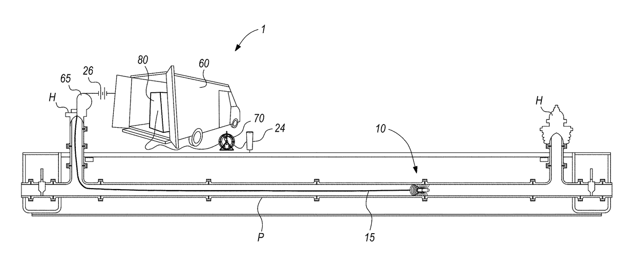
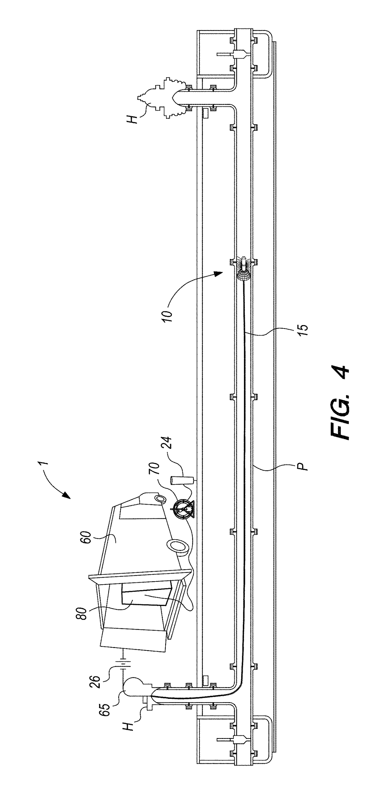
[0046]Referring to the drawings, wherein like reference numerals represent like parts throughout the various drawing figures. The system 1 is consistent with a prior art system described in ASTM (ASTM International, formerly known as “American Society for Testing and Materials”) Standard F2550-13 described as “Standard Practice for Locating Leaks in Sewer Pipes By Measuring The Variation of Electric Current Flow Through the Pipe Wall.” This system 1 can be utilized in underground pressurized (or unpressurized) pipes P such as water or sewer by passing a probe 10 through the pipe P, such as between adjacent fire hydrants H, valves, or other appurtenances to detect defects in the pipe P wall. The system 1 incorporates a launch tube assembly, a reel assembly, and data handling and typically also processing with an on-site PC-based processor, as well as a remote processing location, for efficient and accurate data handling and overall database construction of pipe condition data.

[0047]M...


PUM


Abstract

The system utilizes conductivity equipment as well as a camera, pressure sensor, and acoustic hydrophone within a probe deployed via cable into a pipe to be inspected. The probe completes an electric circuit back to ground when the probe is adjacent a defect through which electric currents can pass, thus producing varying electric current. The camera, incorporated into the electric probe, is utilized for both inspection and navigation through the pipe by providing a close-circuit video data feed. The pressure sensor detects alterations in the pressure and flow field of the fluidic region in the area of a leak. The acoustic hydrophone listens for the sound leaks in a pressurized pipeline. The inspection device is tethered to a cable and inserted a measured distance into the pipeline, typically with the pipeline under pressure, via a launch tube. Multi-sensor data versus pipeline position is thus obtained.

Description

CROSS-REFERENCE TO RELATED APPLICATIONS[0001]This application claims benefit under Title 35, United States Code § 119(e) of U.S. Provisional Application No. 62 / 203,809 filed on Aug. 11, 2015.FIELD OF THE INVENTION[0002]The following invention relates to systems and methods for detecting defects in underground fluid transporting pipes, such as water pipes, which have a potential to leak. More particularly, this invention relates to methods which can utilize a combination of camera, acoustic hydrophone, water pressure sensor, and electric probe through a common defect detection signal cable.BACKGROUND OF THE INVENTION[0003]Pressurized water delivery pipeline systems and other underground pressurized and unpressurized fluid transport pipes can be difficult to inspect due to their hidden location and the substantial costs related with ground excavation. Leaks in such pipes can increase costs associated with operating the pipe due to disruptions and damages, create potential hazards, and...

Claims


Application Information

Patent Timeline
Patent Type & Authority Patents(United States)
IPC IPC(8): G01M3/00G01M3/26G01M3/24G01M3/18G01M3/38G01M5/00G01M3/28G01M3/40
CPCG01M3/40G01M3/18G01M3/246G01M5/0083G01M3/38G01M5/0025G01M3/2823
Inventor HANSEN, CHARLES A.GRABOWSKI, MARK
Owner ELECTRO SCAN
Why Eureka
Try Eureka