
MEMS component including a sound-pressure-sensitive diaphragm element and piezosensitive signal detection

a diaphragm element and piezosensitive technology, applied in the field of mems components, can solve the problems of disadvantageous effect on the microphone sensitivity, large deflection of such diaphragm elements, and large area

Active Publication Date: 2018-04-03
ROBERT BOSCH GMBH
View PDF4 Cites 9 Cited by
  • Summary
  • Abstract
  • Description
  • Claims
  • Application Information

AI Technical Summary

Benefits of technology

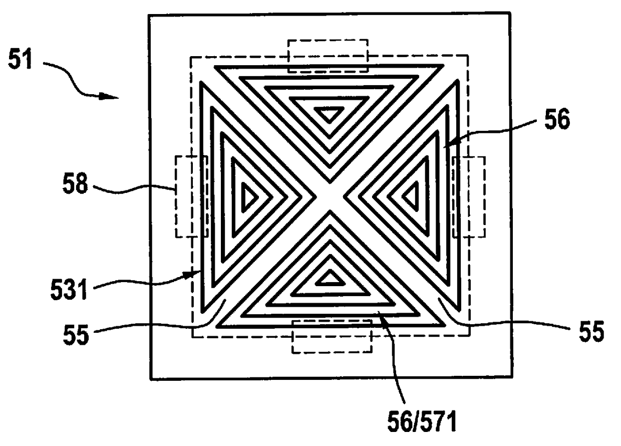
[0005]The present invention provides design measures, by which the stress distribution over the diaphragm surface may be intentionally influenced in the event of deflection of the diaphragm element. In particular, measures are provided by which the mechanical stresses are intentionally introduced into predefined areas of the diaphragm element, to thus amplify the measuring signal.

Problems solved by technology

However, with this diaphragm layout, the flow path between the two sides of the diaphragm element also has a relatively large area, which has a disadvantageous effect on the microphone sensitivity.

Method used


Image

  • MEMS component including a sound-pressure-sensitive diaphragm element and piezosensitive signal detection
  • MEMS component including a sound-pressure-sensitive diaphragm element and piezosensitive signal detection
  • MEMS component including a sound-pressure-sensitive diaphragm element and piezosensitive signal detection

Examples


Embodiment Construction

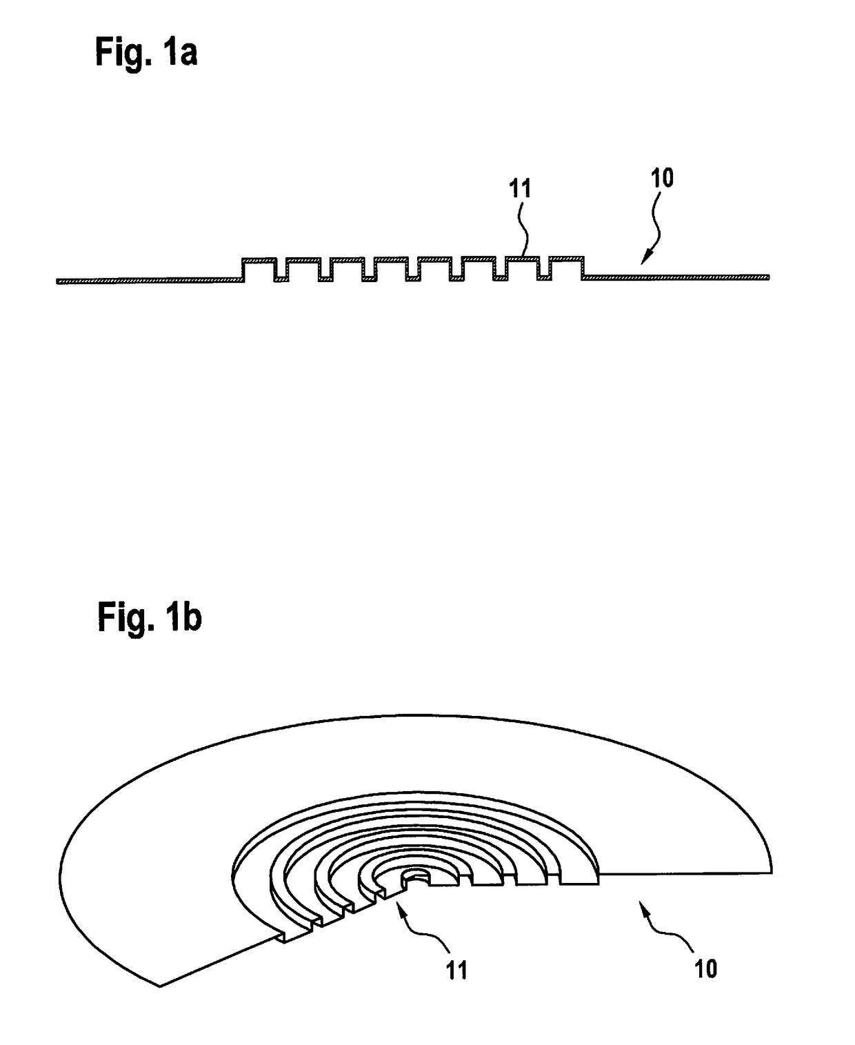
[0019]Circular diaphragm element 10 shown in FIGS. 1a and 1b is a micromechanical structure element, which is implemented in the layer structure of a MEMS component and spans an opening or cavity in the layer structure. Accordingly, diaphragm element 10 is attached via its outer edge area to the layer structure of the MEMS component. The illustration of the component structure is omitted here.

[0020]Shape, size, and thickness and also the material of diaphragm element 10 are selected in such a way that diaphragm element 10 is sound-pressure-sensitive, i.e., it may be used as a microphone diaphragm. The deflections of diaphragm element 10 are detected with the aid of piezosensitive circuit elements, the illustration of which was also omitted here. These piezosensitive circuit elements are typically situated in the area of the attachment of diaphragm element 10 to the layer structure, where the greatest material stretching is to be expected.

[0021]To increase the deformation in the atta...


PUM


Abstract

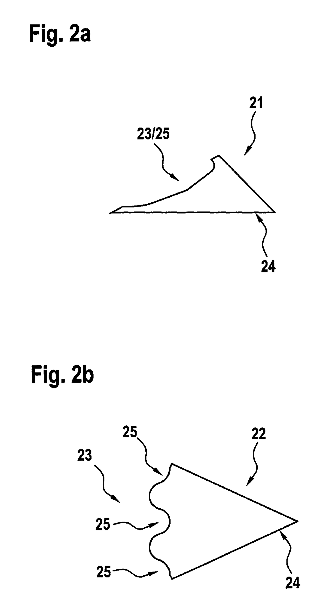
For a MEMS component, in the layer structure of which at least one sound-pressure-sensitive diaphragm element is formed, which spans an opening or cavity in the layer structure and the deflections of which are detected with the aid of at least one piezosensitive circuit element in the attachment area of the diaphragm element, design measures are provided, by which the stress distribution over the diaphragm surface may be influenced intentionally in the event of deflection of the diaphragm element. In particular, measures are provided, by which the mechanical stresses are intentionally introduced into predefined areas of the diaphragm element, to thus amplify the measuring signal. For this purpose, the diaphragm element includes at least one designated bending area, which is defined by the structuring of the diaphragm element and is more strongly deformed in the event of sound action than the adjoining diaphragm sections.

Description

CROSS REFERENCE[0001]The present application claims the benefit under 35 U.S.C. § 119 of German Patent Application No. DE 102015213774.0 filed on Jul. 22, 2015, which is expressly incorporated herein by reference in its entirety.BACKGROUND INFORMATION[0002]The present invention relates to a MEMS component, in the layer structure of which at least one sound-pressure-sensitive diaphragm element is formed, which spans an opening or cavity in the layer structure. The diaphragm element is structured and the deflections of the diaphragm element are detected with the aid of at least one piezosensitive circuit element, which is situated in the area of the attachment of the diaphragm element to the layer structure.[0003]A particular advantage of piezosensitive MEMS microphone components is that—in contrast to capacitive MEMS microphone components—they may be equipped very easily with a “wake-up” functionality. They may thus be provided very easily so that they only consume power if needed, i...

Claims


Application Information

Patent Timeline
Patent Type & Authority Patents(United States)
IPC IPC(8): H04R19/04H04R23/00H04R19/00B81B3/00H04R31/00H04R7/18H04R7/14H04R17/02
CPCH04R7/14B81B3/0072H04R7/18H04R19/005H04R23/006H04R31/006H04R19/04H04R2201/003H04R17/02H04R7/12H04R2207/021
Inventor BUCK, THOMASPURKL, FABIANSTUMBER, MICHAELEHRENPFORDT, RICARDOSCHEBEN, ROLFSTEIN, BENEDIKTSCHELLING, CHRISTOPH
Owner ROBERT BOSCH GMBH
Learn More