Power supply device and method for limiting an output current of a power supply device

a power supply device and output current technology, applied in the direction of power conversion systems, dc-dc conversion, instruments, etc., to achieve the effect of shortening the tim

a power supply device and output current technology, applied in the direction of power conversion systems, dc-dc conversion, instruments, etc., to achieve the effect of shortening the tim

US9941782B2Active Publication Date: 2018-04-10WEIDMULLER INTERFACE GMBH & CO KG

Image

  • Power supply device and method for limiting an output current of a power supply device
  • Power supply device and method for limiting an output current of a power supply device
  • Power supply device and method for limiting an output current of a power supply device

Examples


Embodiment Construction

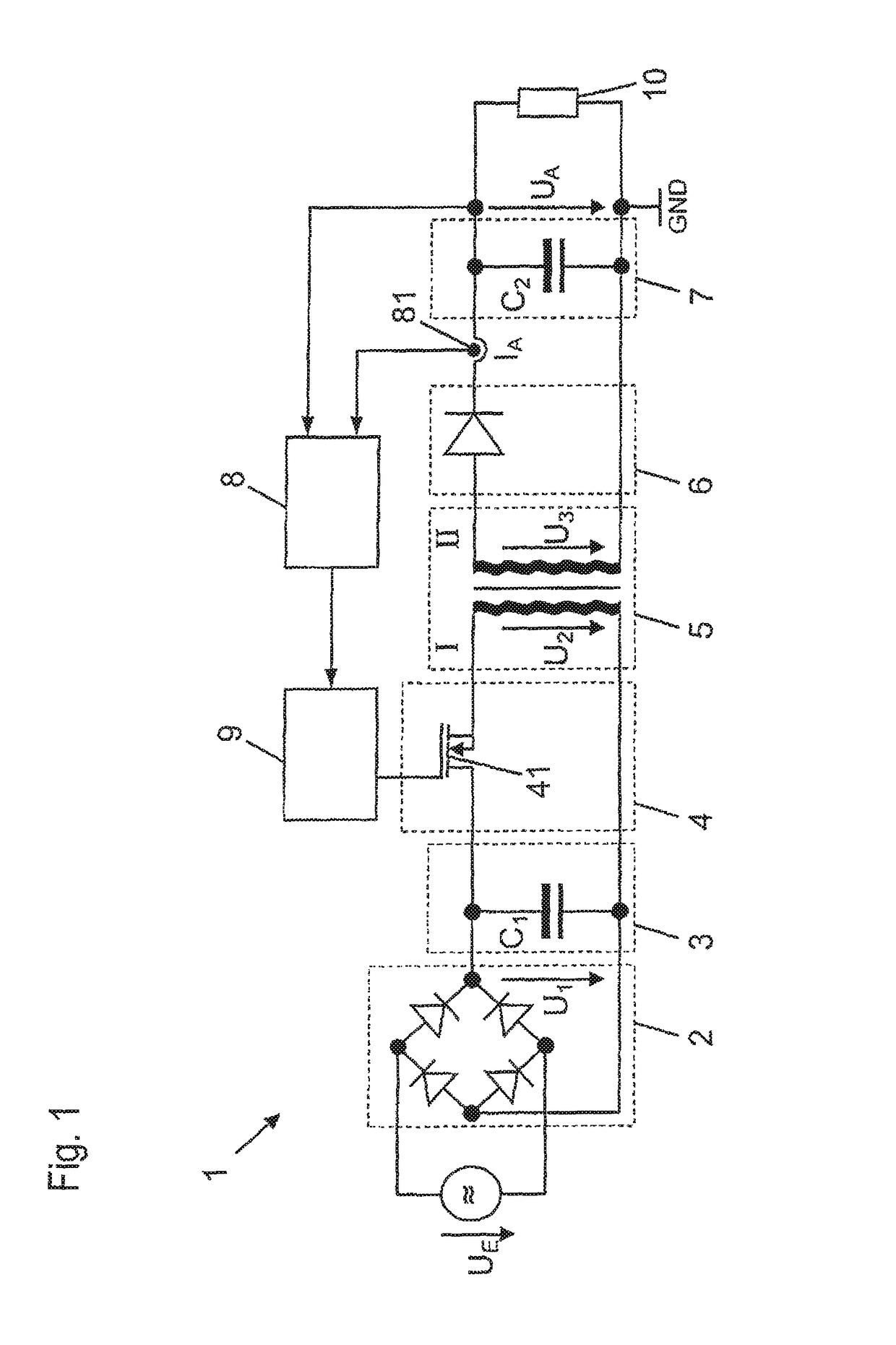
[0025]Referring first more particularly to FIG. 1, a switched-mode power supply system 1 is provided for converting an input voltage UE, in this case an input alternating-current voltage, into an output voltage UA, in this case an output direct-current voltage.

[0026]Input voltage UE is converted by means of a rectifier 2 into a pulsing direct current voltage U1, which is smoothed and / or filtered by means of a smoothing circuit 3. For this purpose, the smoothing circuit 3 has a first smoothing capacitor C1. Alternatively, an active power factor correction circuit (PFC=power factor correction) may also be used as rectifier 2.

[0027]Direct current U1 is fed in a clocked manner to a primary-side (I) winding of a transformer 5, via a switching stage 4 having a switching element 41. Switching stage 4 converts direct-current voltage U1 into a higher frequency alternating-current voltage U2, the frequency of which is significantly higher than the frequency of input alternating current voltag...


PUM


Abstract

A switched-mode power supply system and method for converting an input voltage into an output voltage, including at least one switching stage controlled by a pulse-width modulation circuit in a clocked manner, and a control circuit that influences a pulse-width modulation circuit to vary the level of the output voltage, characterized by the provision of a current limiting circuit which, after a threshold voltage has been exceeded, limits the power supply output current first to an elevated maximum current for a first period of time, and thereafter to a regular maximum current. The control circuit is such that the first period of time for which the output current is limited to the elevated maximum current is dependent on the level of the output current.

Description

REFERENCE TO RELATED APPLICATIONS[0001]This application is a national stage application under 35 C.F.R. § 371 of the PCT International Application No. PCT / EP2014 / 074839 filed Nov. 18, 2014, which claims priority of the German application No. DE 10 2013 113 648.6 filed Dec. 6, 2013.BACKGROUND OF THE INVENTIONField of the Invention[0002]A switched-mode power supply system and method for converting an input voltage into an output voltage, including at least one switching stage controlled by a pulse-width modulation circuit in a clocked manner, and a control circuit that influences a pulse-width modulation circuit to vary the level of the output voltage. A current limiting circuit is provided which, after a threshold voltage has been exceeded, limits the power supply output current first to an elevated maximum current for a first period of time, and thereafter to a regular maximum current. The length of the first period of time is dependent on the level of the output current.Description...

Claims


Application Information

Patent Timeline
10 Apr 2018
Publication
US9941782B2
IPC
H02M1/32; H02H9/02; H02M3/335
CPC
H02M1/32; H02M3/33507; H02H9/02
Inventors
SCHUERMANN, KLAUS; BUSCHKAMP, MICHAEL