Infrared surface light source generating device and method of manufacturing same

a technology of infrared surface light source and generating device, which is applied in the direction of transportation and packaging, vacuum evaporation coating, coating, etc., can solve the problems of increasing the manufacturing cost of infrared light generator, and achieve the effect of wide industrial applicability and low cos

Active Publication Date: 2018-04-24
H&H T +1
View PDF3 Cites 0 Cited by
  • Summary
  • Abstract
  • Description
  • Claims
  • Application Information

AI Technical Summary

Benefits of technology

[0005]A primary object of the present invention is to provide an infrared surface light source generating device that is able to emit far infrared rays without the need of any additional electric heating element. The device includes a carbon material layer that is able to emit far infrared rays when being heated by an amount of external low-power energy, even if the device does not include any electric heating element; and the device can be manufactured without the need of applying an infrared paint or mixing ceramic powder with graphite powder. Further, the infrared surface light source generating device provided according to the present invention has excellent infrared emissivity, particularly in the far infrared region.
[0006]Another object of the present invention is to provide a method of manufacturing the above infrared surface light source generating device. The method adopts simplified manufacturing process and uses easily available materials to make the infrared surface light source generating device, enabling the device to have reduced manufacturing cost and largely increased industrial applicability.
[0019]The infrared surface light source generating device of the present invention is characterized in that the carbon material layer is able to emit far infrared rays when it is heated by an amount of external energy, such as an electric source or a light source, to a temperature above 36° C. The method of manufacturing infrared surface light source generating device according to the present invention is characterized in using a simplified manufacturing process, in which a substrate layer is provided and then a carbon material layer is formed on a surface of the substrate layer to complete the infrared surface light source generating device. The device so manufactured is low in cost and has wide industrial applicability.

Problems solved by technology

Therefore, the conventional infrared light generator 1 has a relatively complicate structure and the manufacture thereof involves a complicated manufacturing process, which inevitably increase the manufacturing cost of the infrared light generator 1.

Method used


Image

  • Infrared surface light source generating device and method of manufacturing same
  • Infrared surface light source generating device and method of manufacturing same
  • Infrared surface light source generating device and method of manufacturing same

Examples


Embodiment Construction

[0038]The present invention will now be described with some preferred embodiments thereof and by referring to the accompanying drawings. For the purpose of easy to understand, elements that are the same in the preferred embodiments are denoted by the same reference numerals.

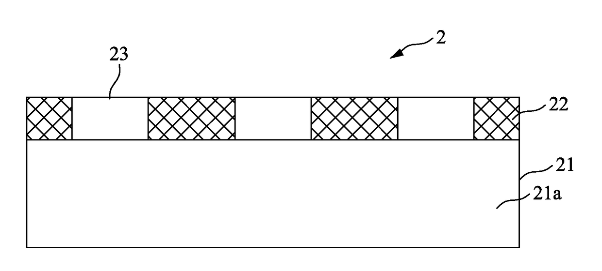
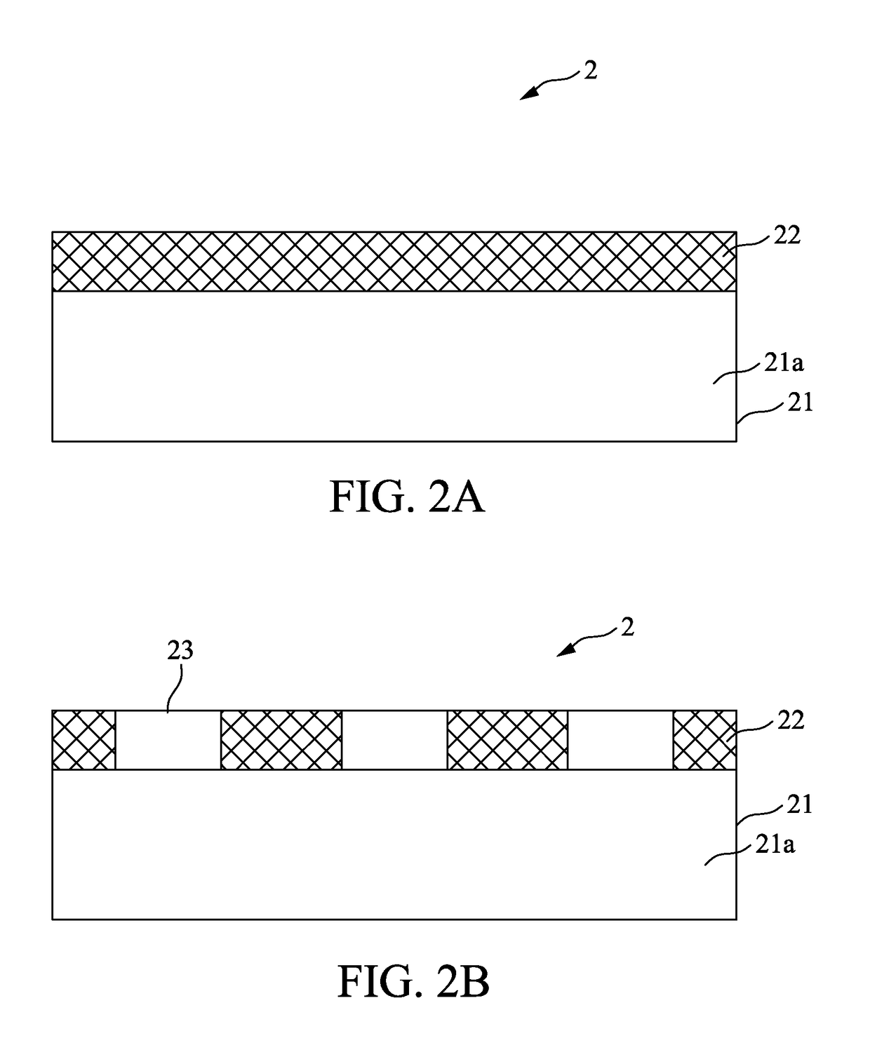
[0039]Please refer to FIG. 2A, which is a schematic sectional view showing the structure of an infrared surface light source generating device according to a first embodiment of the present invention. For the purpose of conciseness and clarity, the present invention is also briefly referred to as the device and generally denoted by reference numeral 2 herein. As shown in FIG. 2A, the device 2 includes a substrate layer 21 formed of an insulation substrate 21a and a carbon material layer 22 formed of a pure carbon material. The carbon material layer 22 is so structured that it has a thickness smaller than 1 μm and a sheet resistance value ranged between 0.01 and 1000Ω / □. The sheet resistance is adjustable by contr...


PUM

PropertyMeasurementUnit
thicknessaaaaaaaaaa
temperatureaaaaaaaaaa
sheet resistanceaaaaaaaaaa

Abstract

An infrared surface light source generating device includes a substrate layer and a carbon material layer formed on a surface of the substrate layer and having a sheet resistance value ranged between 0.01 and 1000Ω / □. The carbon material layer is able to emit far infrared rays when it is heated by an amount of external low-power energy to a temperature above 36° C. A method of manufacturing the above infrared surface light source generating device is also disclosed. The method includes the steps of (A) providing a substrate layer and (B) forming a carbon material layer that is located on a surface of the substrate layer and has a sheet resistance value ranged between 0.01 and 1000Ω / □. Since the method involves only a simplified manufacturing process, the infrared surface light source generating device can be manufactured at reduced cost.

Description

FIELD OF THE INVENTION[0001]The present invention relates to an infrared surface light source generating device, and more particularly to an infrared surface light source generating device that is able to emit far infrared rays without the need of any electric heating element. The present invention also relates to a method of manufacturing such infrared surface light source generating device.BACKGROUND OF THE INVENTION[0002]FIG. 1 schematically shows a conventional infrared light generator 1, which includes a substrate 11, an electric heating element 12 located on a top of the substrate 11 and capable of producing heat when being supplied with electric current, and an infrared emitting element 13 located on a top of the electric heating element 12 for absorbing heat energy and thereby emitting infrared rays. The infrared emitting element 13 includes an infrared paint composed of graphite and carbon black. The ratio of the graphite to the carbon black is ranged from 1:1 to 1:2.[0003]...

Claims


Application Information

Patent Timeline
Patent Type & Authority Patents(United States)
IPC IPC(8): B32B3/24C23C14/02H05B3/20H05B3/14H05B3/26C23C14/06C23C14/34B82Y20/00
CPCC23C14/0605C23C14/025C23C14/34H05B3/14H05B3/20H05B3/26H05B3/145Y10T428/24331B82Y20/00H01K1/06H01K1/20
Inventor HU, CHUAN LING
Owner H&H T
Why Eureka
Try Eureka