Apparatus for the continuous manufacture of a spunbond web

a technology of yarn and yarn, which is applied in the direction of filament/thread forming, filament manufacturing, non-woven fabrics, etc., can solve the problems of high cost, complex needle-punching devices, and increased disadvantages, and achieves low cost, functional reliability, and simple

Active Publication Date: 2018-04-24
REIFENHAUSER GMBH & CO MASCHFAB
View PDF13 Cites 0 Cited by
  • Summary
  • Abstract
  • Description
  • Claims
  • Application Information

AI Technical Summary

Benefits of technology

[0003]The object of the invention is therefore to provide an apparatus of the above-mentioned type with which isotropic properties of the nonwoven web or the spunbond fabric can be obtained in the machine direction (MD) and transversely to the machine direction (CD) in a simple, low-cost, and functionally reliable manner. The object, in particular, is to obtain identical or substantially identical strength properties in the machine direction (MD) and transverse to the machine direction (CD).
[0004]Another object of the invention is to provide a corresponding product and / or a corresponding spunbond web.
[0005]To attain the object, the invention provides an apparatus for the continuous manufacture of a spunbond web (S) from filaments, in particular aerodynamically stretched filaments—preferably from thermoplastic plastic using a spinneret, a cooling chamber for cooling the filaments, a stretcher, and a deposition device for the deposition of the filaments to form the spunbond web, where at least one filament guide having a plurality of filament-guide gaps open toward the stretcher is provided between the stretcher and the deposition device, wherein the filament guide or at least one guide part of the filament guide can be moved such that the filament-guide gap or the stretcher-side openings thereof are displaced in particular transversely to the travel direction of the spunbond web such that the filaments or filament bundles guided along or through the filament-guide gap are given an (additional) transverse orientation to the travel direction of the spunbond web when deposited on the deposition device. It lies within the scope of the invention that the filaments are endless filaments that are produced using a spunbond process.
[0006]The conveyance or travel direction of the spunbond web means, in particular, the travel direction of the deposition device. Preferably at least one conveyor belt is used as the deposition device. It lies within the scope of the invention that the filaments are initially produced as a filament curtain or filament curtain that is continuous or substantially continuous transversely to the travel direction. It also lies within the scope of the invention that the stretcher has a continuous stretching gap that is elongated transversely to the travel direction for this purpose. This stretching gap advantageously extends at least across the greatest portion of the width of the deposited spunbond web transversely to the travel direction. The filament guide according to the invention or the filament-guide gaps thereof separate filaments or filament bundles from the continuous filament curtain that are influenced and / or redirected according to the invention and are deposited on the deposition device accordingly.
[0007]Monocomponent filaments and / or multicomponent filaments or bicomponent filaments can be used as filaments within the scope of the invention. Preferably, the filaments substantially comprise a thermoplastic plastic, for example made of a polyolefin, preferably of polyethylene and / or polypropylene or a polyester or a polyamide. According to one embodiment, the filaments have a titer of at least 1 denier, preferably of at least 1.5 denier. It is recommended that the spunbond web has a basis weight of at least 20 g / m2, preferably at least 40 g / m2 and, according to one embodiment, at least approximately 50 g / m2, for example.
[0008]It lies within the scope of the invention that the cooling air fed into the cooling chamber can be supplied from an air supply chamber. According to one embodiment of the invention, the air supply chamber has at least two or only two compartments disposed vertically one above the other. From these compartments, the cooling chamber can supply cooling air having different temperatures. According to a particularly preferable embodiment, which is particularly significant within the scope of the invention, an assembly comprising the cooling chamber and the stretcher—apart from the air supply in the cooling chamber—forms a closed system. Basically, however, it is also possible to work with a so-called open system. It is recommended that the deposition device of the apparatus is a conveyor belt or an endlessly circulating conveyor belt. The filaments are emitted by the spinneret and are preferably guided along a vertical or substantially vertical flow path from the spinneret to the deposition device or the conveyor belt. The vertical or substantially vertical filament curtain / filament curtain undergoes a deflection in the filament guide according to the invention.

Problems solved by technology

As a result, the deposited filaments have different properties in the machine direction than transversely to the machine direction, which is unwanted, for example the deposited filaments have less strength transversely to the machine direction than in the machine direction.
Certain needle-punching measures for consolidation the nonwoven web can increase these disadvantageous effects even further.
The result obtained therewith left much to be desired, however, not to mention that such needle-punching devices are complex and expensive.

Method used


Image

  • Apparatus for the continuous manufacture of a spunbond web
  • Apparatus for the continuous manufacture of a spunbond web
  • Apparatus for the continuous manufacture of a spunbond web

Examples


Embodiment Construction

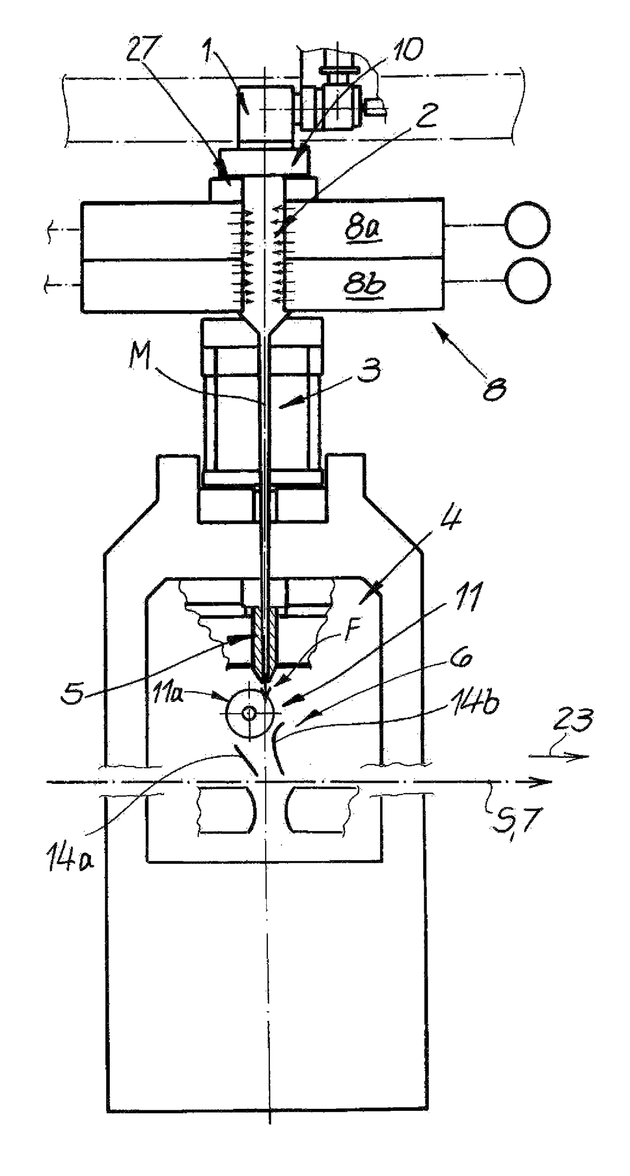
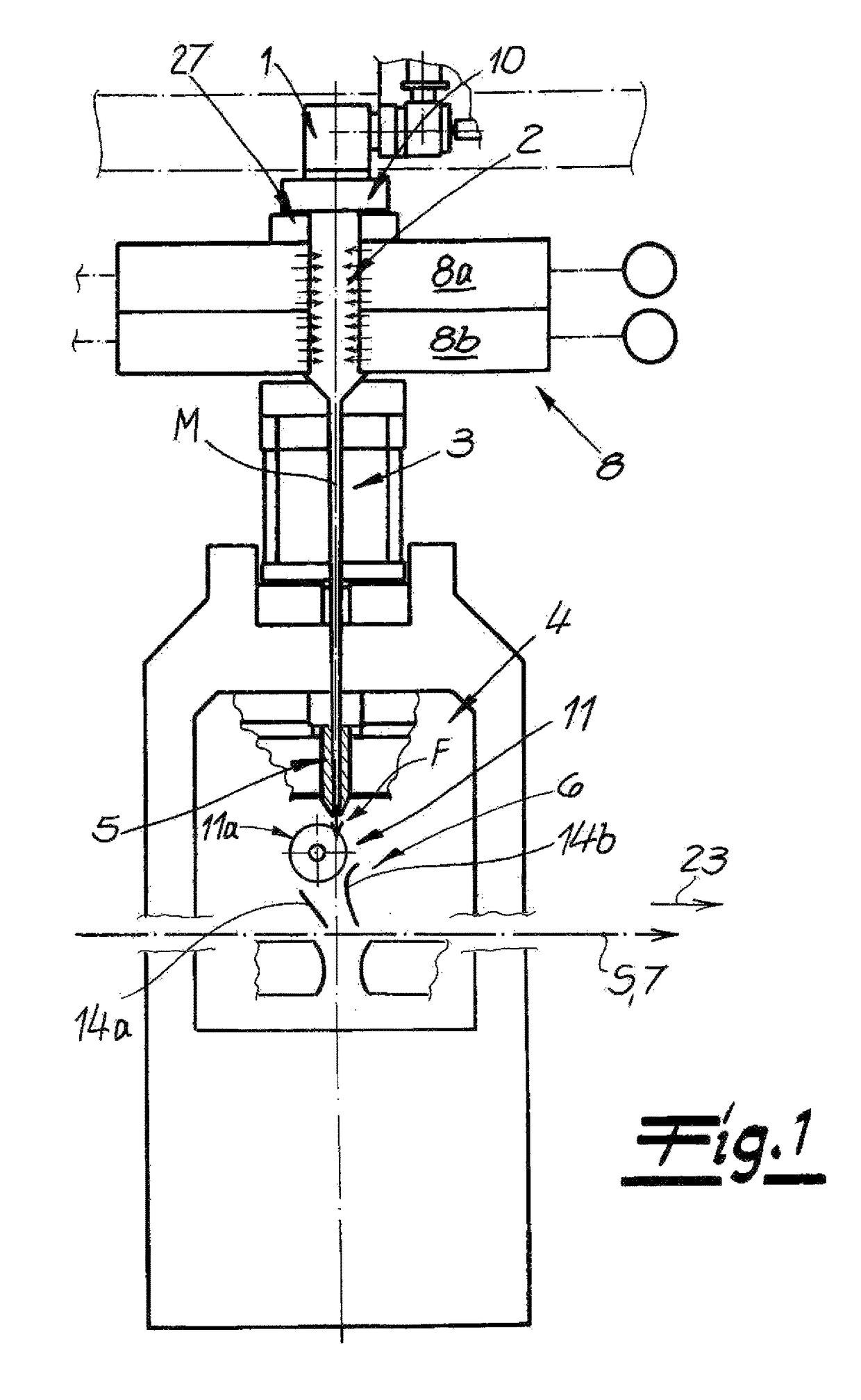
[0045]FIG. 1 shows an apparatus for the continuous manufacture of a spunbond web S from aerodynamically stretched filaments of thermoplastic plastic. The apparatus has a spinneret 1 and a cooling chamber 2 underneath the spinneret and into which process air can be introduced in order to cool the filaments. Adjoining the cooling chamber 2 is an intermediate passage 3 followed in the direction of travel of the filaments, by a stretcher 4 having a stretching passage 5. Adjoining the stretching passage 5 is a deposition unit 6. A deposition device as a continuously circulating conveyor belt 7 for the deposition of the filaments for the spunbond web S is provided underneath the deposition unit 6. Here, the assembly comprising the cooling chamber 2, the intermediate passage 3, and the stretcher 4—except for the air supply in the cooling chamber 2—is a closed system. A further air supply is therefore not provided in this assembly.

[0046]FIG. 1 also shows that an air supply chamber 8 next to...


PUM

PropertyMeasurementUnit
frequencyaaaaaaaaaa
frequencyaaaaaaaaaa
frequencyaaaaaaaaaa

Abstract

An apparatus for the continuous manufacture of a spunbond web from aerodynamically stretched thermoplastic filaments has at least one spinneret, a cooling chamber for cooling the filaments, a stretcher, and a deposition device for the deposition of the filaments to form the spunbond web. At least one filament guide having a plurality of filament-guide gaps opens toward the stretcher between the stretcher and the deposition device, and the filament guide or at least one guide part of the filament guide can be moved such that the filament-guide gap or the stretcher-side openings thereof are displaced transversely to the travel direction of the spunbond web. Thus the filaments or filament bundles guided along or through the filament-guide gap are given a transverse orientation to the travel direction of the spunbond web when deposited onto the deposition device.

Description

FIELD OF THE INVENTION[0001]The invention relates to an apparatus for the continuous manufacture of a spunbond web from aerodynamically stretched filaments, preferably from thermoplastic plastic.BACKGROUND OF THE INVENTION[0002]An apparatus of the above-described type is basically known from practical applications. In this connection, it has been proven effective to spin, cool, and stretch the filaments with a spinner and, after expanding the thus produced filament bundle, to then form the spunbond web by depositing the filaments on a deposition device that is usually an endless conveyor belt. In the apparatus known from practical applications, the spunbond web that has been deposited onto the conveyor belt is subjected to additional processing steps. Many spunbond fabrics produced with the known measures leave much to be desired with respect to their mechanical properties, in particular, such as tensile strengths, tear propagation resistances, isotropy, dimensional stability, etc. ...

Claims


Application Information

Patent Timeline
Patent Type & Authority Patents(United States)
IPC IPC(8): D04H3/16D01D11/04D01D5/092D01D5/14D01D11/00D04H3/005D01D5/098D01D5/12D04H3/02
CPCD04H3/16D01D5/092D01D5/0985D01D5/12D04H3/02D01D11/00D01D11/04D04H3/005D01D5/14
Inventor SOMMER, SEBASTIANMARKES, HARALDKLEIN, ALEXANDEROEZGOEREN, EMINGORETZKI, FELIX
Owner REIFENHAUSER GMBH & CO MASCHFAB
Why Eureka
Try Eureka