Laryngascope free airway device

a free airway and laryngoscope technology, applied in the field of medical airway management devices, can solve the problems of inability to quickly correct the intubation, the inability to visualize the vocal cord, and the risk of the laryngoscope causing significant patient harm,

Inactive Publication Date: 2018-05-01
SUN YANG
View PDF12 Cites 13 Cited by
  • Summary
  • Abstract
  • Description
  • Claims
  • Application Information

AI Technical Summary

Benefits of technology

[0035]The base is coupled towards the mid or distal segment of the tube system and the leading edge of the base can be configured to reach the upper esophageal sphincter which may be able to block regurgitation. The base can also serve as a platform for an esophageal gastric drainage tube which can be connected to a suction device. Alternatively, an oral gastric tube can be passed through the oral-gastric-drainage tube, through the esophageal sphincter and into the stomach to empty its contents. The end of the air tube is configured with one or more air expansion projections. In their nature relaxed position, the four projections are orientated parallel with the air tube longitudinal axis. The projections provide a guide for an advancing endotracheal tube and can push away tissue blocking the airway.

Problems solved by technology

However, a blade laryngoscope has significant patient risks.
These include dental injury, airway soft tissue injury, and further injury to a patient's with a neck injury caused by neck manipulation during blade insertion.
Further, visualization of vocal cords can be difficult or impossible.
Such improper intubation, if not quickly corrected can have fatal consequences.
However, a variety of trauma and clinical settings can make direct or indirect visual observation very difficult if not impossible.
However, these LMA blind intubation devices are easily positioned incorrectly.
Even when ventilation can still be carried out, an LMA can be inefficient and increase the risk of aspiration.
Further, even when this blind intubation device is correctly inserted and positioned, sliding an endotracheal tube alone the elongated air tube into a trachea is difficult.
Another problem with these devices is that the device can push or catch the epiglottis moving it over the glottis and obstruct the airway.
Another disadvantage of an LMA is that it often poorly seals making it easier for regurgitation and aspiration.
This design has achieved limited acceptance and has a number of limitations.
First, the ILMA has a metal handle with a pronounced curved region making it difficult to insert into a patient's mouth.
Such precise position is often hard to achieve.
One problem that the ILMA can exhibit is that the tip can become folded at the back of the oropharynx, or the epiglottis could be folded down, or the endotracheal tube can become lodged against the edge of vocal cords.
These problems can make the passing of an endotracheal tube very difficult.
And in addition, ILMA requires a special endotracheal tube which is inconvenient and more costly.
This stiff leading tip increases the risk of soft tissue injury during the insertion.
Additionally, the tip projects outwardly from the LMA structure thereby lengthening the device and thereby increasing the difficulty of inserting the device.
In the prior art patent U.S. Pat. No. 8,128,071, optical fibers were added to gain visualization of the laryngeal anatomy, but this device also suffers from the limitations stated above.
However, there is no assurance of stable alignment of the device with respect to the laryngeal opening.
Therefore, an endotracheal tube can be misguided and cause incorrect intubation and laryngeal trauma.
These requirements make intubation very difficult to be achieved quickly and reliably.
However the anatomy of laryngeal pharynx is highly variable and it is very difficult to have an universal device to fit each individual's anatomy.
Therefore, a poor air seal is often achieved which easily causes aspiration.
Further, if positive ventilation applied, air can easily flow into stomach resulting in artificial ventilation failure and aspiration.
While this technique had been considered the gold standard in case of awake intubation, often the tip of the fiber optic scope is touching and bent against the wall of a patient's airway obstructing the view.
Additionally, secretions and blood often block the view of the tip of fiber optic scope, all those reasons easily cause the intubation to fail.
Further, this technique is time consuming not suitable in emergence situations and requires significant skill and training.

Method used


Image

  • Laryngascope free airway device
  • Laryngascope free airway device
  • Laryngascope free airway device

Examples


operational example

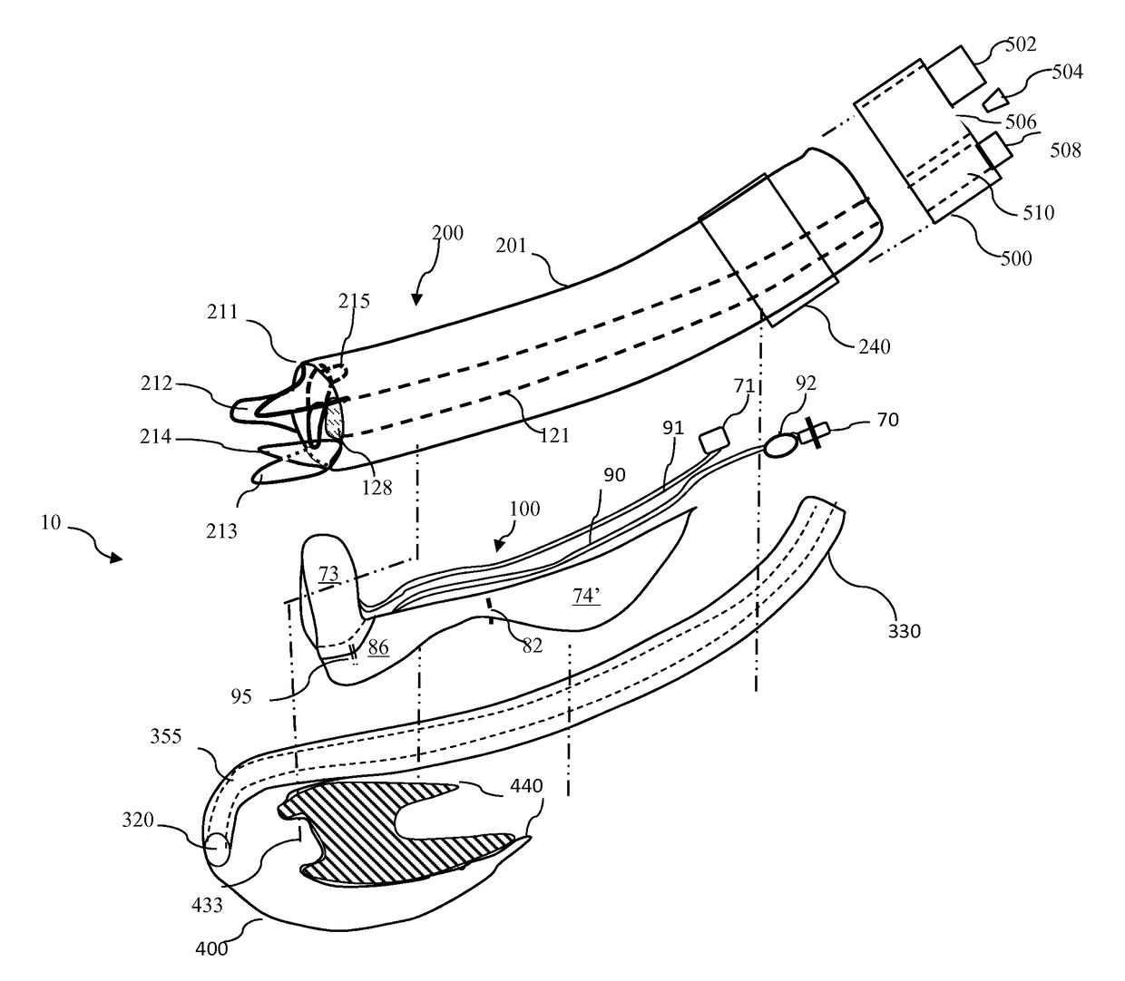
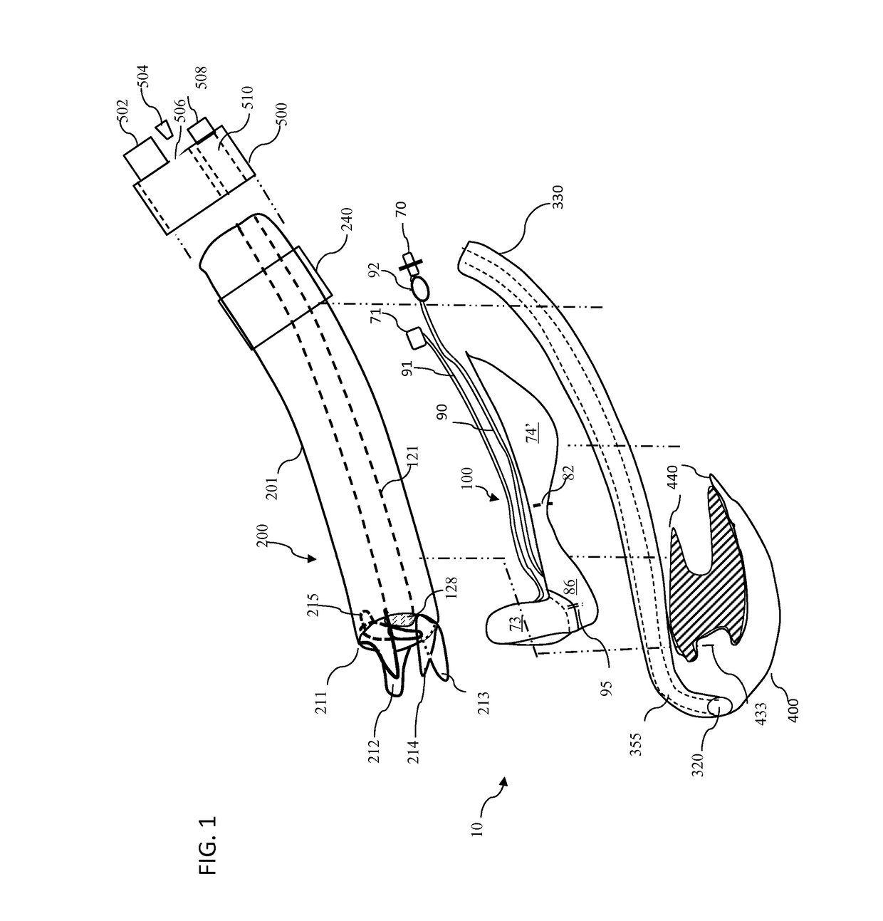
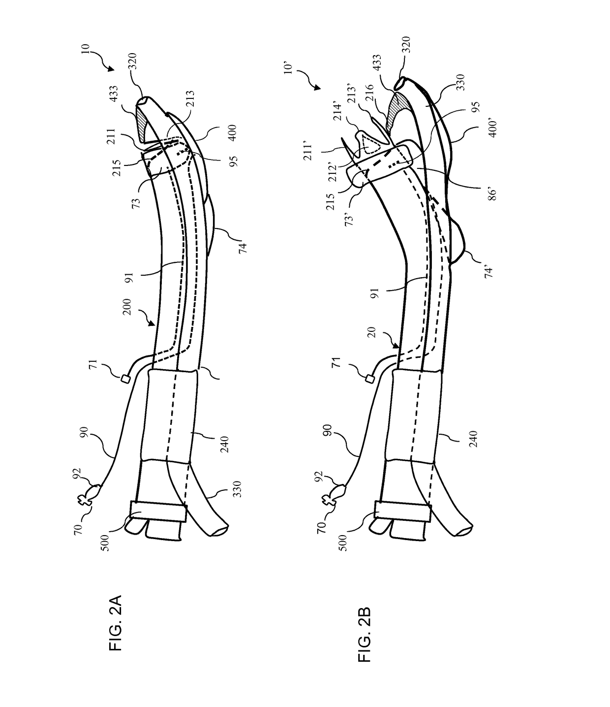
[0102]In operation the LFA device is first prepared for insertion. The stylet is inserted into an ETT (endotracheal tube) lumen. The sickle-shaped tip of the stylet is extended beyond the ETT's distal end opening. Then the endotracheal tube can be lubricated and inserted into the air tube or as mentioned above or can have only the stylet inserted into the LFA without an endotracheal tube. The balloon system is deflated, so the tube system and the base will be in close proximity to each other. The one or more expansion projection are tucked under the barb of the base. The LFA is well lubricated. An operator will use one hand to open the mouth and will use the other hand to insert LFA into the mouth. Then an operator uses one or two fingers push down the middle segment of LFA to flex the LFA to follow the curvature of the middle line of natural curvature of the hard palate, soft palate and pharynx until the LFA reaches the proper position. Proper position can be where the leading edge...


PUM


Abstract

An airway device configured for intubation under blind or optionally under indirect vision of a fiber optic scope. It also configured to be used as a supraglottic airway device supporting external breathing or anesthesia circuits. The device comprises a tube system with expansion projections, a base, one or more inflation balloons, and a gastric suction tube. The device can include a stylet to guide endotracheal tube during intubation. The tube system can include an air tube and fiber-optic-probe tube. The balloon system can move the end of the tube system anteriorly to align it with the laryngeal opening. The balloon system can seal the airway leakage for low positive pressure ventilation for the device to operate as a supraglottic airway device. The inflation balloon and expansion projection can displace tissue that can block the airway path. The base can carry esophageal gastric drainage tube to the upper esophageal sphincter to block and drain gastric content regurgitation.

Description

CROSS REFERENCE TO OTHER APPLICATIONS[0001]This application claims priority under 35 U.S.C. § 119(e) of the U.S. provisional patent application Ser. No. 61 / 964,419 filed on Jan. 6, 2014 entitled “Laryngoscope Free Airway.” The provisional patent application Ser. No. 61 / 964,419 filed on Jan. 6, 2014 entitled “Laryngoscope Free Airway” is hereby incorporated by reference.FIELD OF INVENTION[0002]The present invention relates to medical airway management devices and methods for blindly, rapidly and gently intubating people and animals in routine surgical cases, intensive care unit, and emergency resuscitation. The present invention is designed to be easily used by with minimal training of medical personal, in in-hospital, pre-hospital, surgical clinical, not limited to specialized medical specialties.[0003]Further, the invention relates to airway devices that supports a visualization system, including fiber-optic imaging systems, for visualization of the larynx inlet during and after in...

Claims


Application Information

Patent Timeline
Patent Type & Authority Patents(United States)
IPC IPC(8): A61B1/00A61M16/04A61B1/267
CPCA61M16/0497A61B1/267A61M16/0459A61B1/00165A61B1/00137A61B1/00082A61M16/0463A61M16/0415A61M16/0429A61M2210/0656A61M2210/105
Inventor SUN, YANG
Owner SUN YANG
Why Eureka
Try Eureka