Blue phase liquid crystal display panel

a liquid crystal display and blue phase technology, applied in non-linear optics, instruments, optics, etc., can solve the problems of high drive voltage, limited penetration depth of lateral electric field generated by parallel electrodes, and high cost, so as to reduce external drive voltage and ensure the safety of using liquid crystal display devices

Active Publication Date: 2018-05-01
WUHAN CHINA STAR OPTOELECTRONICS TECH CO LTD
View PDF18 Cites 2 Cited by
  • Summary
  • Abstract
  • Description
  • Claims
  • Application Information

AI Technical Summary

Benefits of technology

[0008]According to the blue phase liquid crystal display panel provided by the present disclosure, the pixel electrode extends towards the first common electrode, enabling the pixel electrodes each to have an extending length extending towards the first common electrode. In this case, an electric field is generated between the pixel electrode and the first common electrode, and between the pixel electrode and the second common electrode. By configuring the extending length of the pixel electrode, the electric field generated between the pixel electrode and the first common electrode, and between the pixel electrode and the second common electrode can have a larger horizontal component in the liquid crystal layer, thereby rendering the intensity of electric field higher in the liquid crystal layer in the horizontal direction. The higher intensity of electric field enables the liquid crystal molecules in the blue phase liquid crystals to have a higher deformation rate in the horizontal direction, thereby reducing the external drive voltage of the blue phase liquid crystal. It should be noted that the pixel electrodes each can extend from the second common electrode to the first common electrode, or alternatively extend from the lower substrate to the first common electrode. In addition, the horizontal direction in the liquid crystal layer in the present disclosure refers to the direction parallel to the upper substrate and the lower substrate, and the horizontal electric field refers to the electric field along the horizontal direction, which can also be referred to as lateral electric field.
[0009]In some embodiments, the pixel electrodes each are provided with an insulating layer at an end facing the first common electrode. The insulating layer is used to enable the pixel electrode to approach the first common electrode on the upper substrate to the maximum, and in the meanwhile, to avoid the contact of the extending pixel electrodes with the first common electrode, thereby protecting the pixel electrode and avoiding any display problems caused by the pressure on the upper substrate.
[0010]In some embodiments, the first common electrode completely covers the upper substrate, the second common electrode completely covers the lower substrate, and the pixel electrodes extend from the second common electrode in an insulating manner. According to such arrangement, the first common electrode and the second common electrode completely cover the corresponding substrate, thereby simplifying the manufacturing process of the first common electrode and the second common electrode.
[0012]In some embodiments, the third common electrode is provided with an insulating layer at an end facing the first common electrode. The insulating layer protects the third common electrode, so as to avoid any display problems caused by the pressure on the upper substrate.
[0017]In some embodiments, the extending length of the pixel electrode is larger than or equal to half of the distance between the upper substrate and the lower substrate, and is smaller than the distance between the upper substrate and the lower substrate. By configuring the extending length of the pixel electrode reasonably within the above distance range, the intensity of the electric field in the liquid crystal layer in the horizontal direction can be effectively improved.
[0018]Compared with the existing technologies, the present disclosure provides more electrode structures which render the intensity of electric field higher in the liquid crystal layer in the horizontal direction, thereby reducing the external drive voltage used for driving the blue phase liquid crystals. In addition, to provide an insulating layer at the extending end of the pixel electrodes ensures the safety of using the liquid crystal display device.

Problems solved by technology

However, blue phase liquid crystals suffer from the problem of requiring a high drive voltage.
However, as for the method of improving the performance of blue phase liquid crystal materials, for example, preparing a blue phase liquid crystal material with a large Kerr constant, it involves a very complex process of synthesizing the blue phase liquid crystal material, and therefore the cost is very high.
As for the method of optimizing the electrode structures, according to the drive method with IPS structure, the penetration depth of the lateral electric field generated by the parallel electrodes is limited.
Therefore, a high drive voltage is still required.

Method used


Image

  • Blue phase liquid crystal display panel
  • Blue phase liquid crystal display panel
  • Blue phase liquid crystal display panel

Examples


Embodiment Construction

[0028]The present disclosure will be explained in detail with reference to the accompanying drawings.

[0029]The details provided herein are merely exemplary in nature, and serve only as examples in discussing the embodiments of the present disclosure, as well as the most useful and comprehensible description about the present disclosure with respect to the principle and concepts thereof. These descriptions are provided only for basic understanding of the present application. One skilled in the art can clearly understand, based on the description and the accompanying drawings, how to implement the present disclosure in different ways.

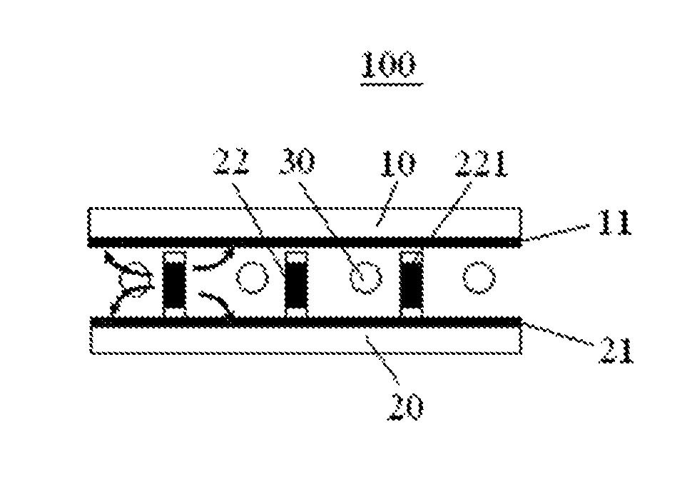
[0030]FIG. 1 schematically shows the structure of a blue phase liquid crystal display panel 100 according to embodiment 1 of the present disclosure. The blue phase liquid crystal display panel 100 comprises an upper substrate 10 and a lower substrate 20 which are disposed opposite to each other, and blue phase liquid crystals 30 provided between the upper...


PUM

PropertyMeasurementUnit
electric fieldaaaaaaaaaa
lengthaaaaaaaaaa
optical isotropyaaaaaaaaaa

Abstract

Disclosed is a blue phase liquid crystal display panel which includes an upper substrate and a lower substrate which are disposed opposite to each other, and blue phase liquid crystals provided between the upper substrate and the lower substrate. The upper substrate is provided with a first common electrode on a side facing the blue phase liquid crystals, and the lower substrate is provided with a second common electrode and a plurality of pixel electrodes on a side facing the blue phase liquid crystals. The pixel electrodes each extend towards the first common electrode, thus forming a horizontal electric field between the upper substrate and the lower substrate. According to the present disclosure, higher horizontal field intensity can be achieved so that the external drive voltage of the blue phase liquid crystals can be greatly decreased.

Description

CROSS REFERENCE TO RELATED APPLICATIONS[0001]The present application claims the priority of Chinese patent application CN201510380874.9, entitled “Blue phase liquid crystal display panel” and filed on Jun. 30, 2015, the entirety of which is incorporated herein by reference.TECHNICAL FIELD[0002]The present disclosure relates to the technical field of liquid crystal displays, and in particular, to a blue phase liquid crystal display panel.TECHNICAL BACKGROUND[0003]In the technical field of liquid crystal displays, blue phase liquid crystals have been widely used in liquid crystal display devices in virtue of their excellent properties. For instance, due to the optical isotropy of blue phase liquid crystals, the liquid crystal display devices using blue phase liquid crystals have advantages such as high response rate, wide viewing angle, excellent dark state, etc. Meanwhile, being different from other liquid crystal display devices, liquid crystal display devices using blue phase liqui...

Claims


Application Information

Patent Timeline
Patent Type & Authority Patents(United States)
IPC IPC(8): G02F1/1343G02F1/1333
CPCG02F1/134363G02F1/133345G02F2201/123G02F2201/121G02F1/134309G02F1/13793G02F1/134381
Inventor TANG, YUEJUN
Owner WUHAN CHINA STAR OPTOELECTRONICS TECH CO LTD
Why Eureka
Try Eureka