Magnetic roll

a magnetic roll and roll-type technology, applied in the field of rolling or rollers, can solve the problems of inability to attract and separate ferrous materials in conventional and known magnetic roll configurations, and achieve the effect of enhancing magnetic flux density and magnetic attractive strength, and low magnetic susceptibility

Active Publication Date: 2018-05-08
BUNTING MAGNETICS
View PDF48 Cites 6 Cited by
  • Summary
  • Abstract
  • Description
  • Claims
  • Application Information

AI Technical Summary

Benefits of technology

[0012]The cumulative effects of the invention's underlying magnetic armature, alternating circumferential pole series, and axial pole series advantageously enhance magnetic flux density and magnetic attractive strength over the entirety of the outer surface of the roll. Such magnetic strength enhancements allow the magnetic roll to be effectively utilized for magnetic separation of low magnetic susceptibility stainless steel scrap metal.
[0013]Accordingly, objects of the instant invention include the provision of a magnetic roll which incorporates structures, as described above, and which arranges those structures in relation to each other in manners described above for the performance of the beneficial functions described above.

Problems solved by technology

In such circumstances, the conventional and known magnetic roll configurations often unacceptably attract and separate the ferrous materials.

Method used


Image

  • Magnetic roll
  • Magnetic roll
  • Magnetic roll

Examples


Embodiment Construction

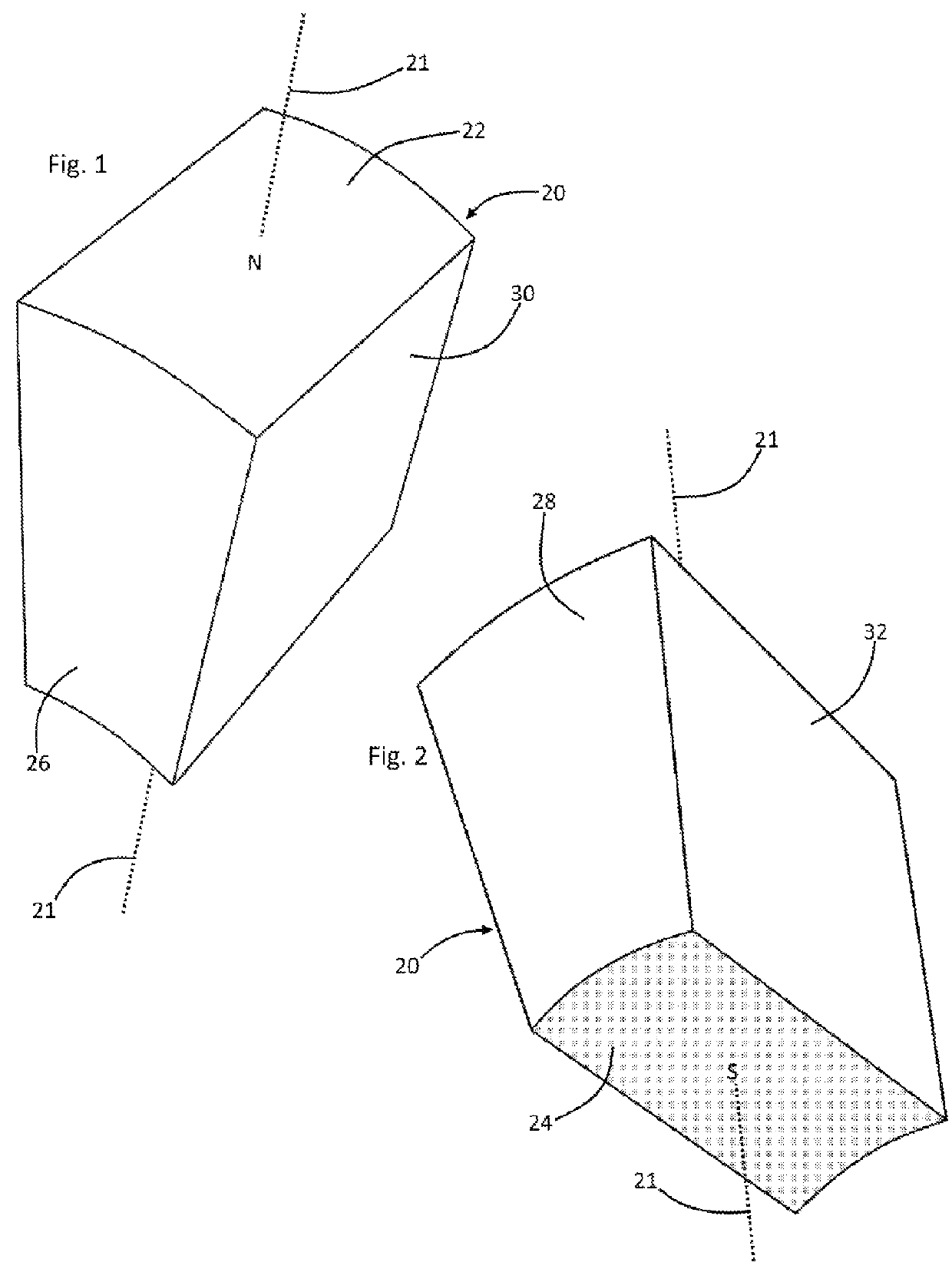
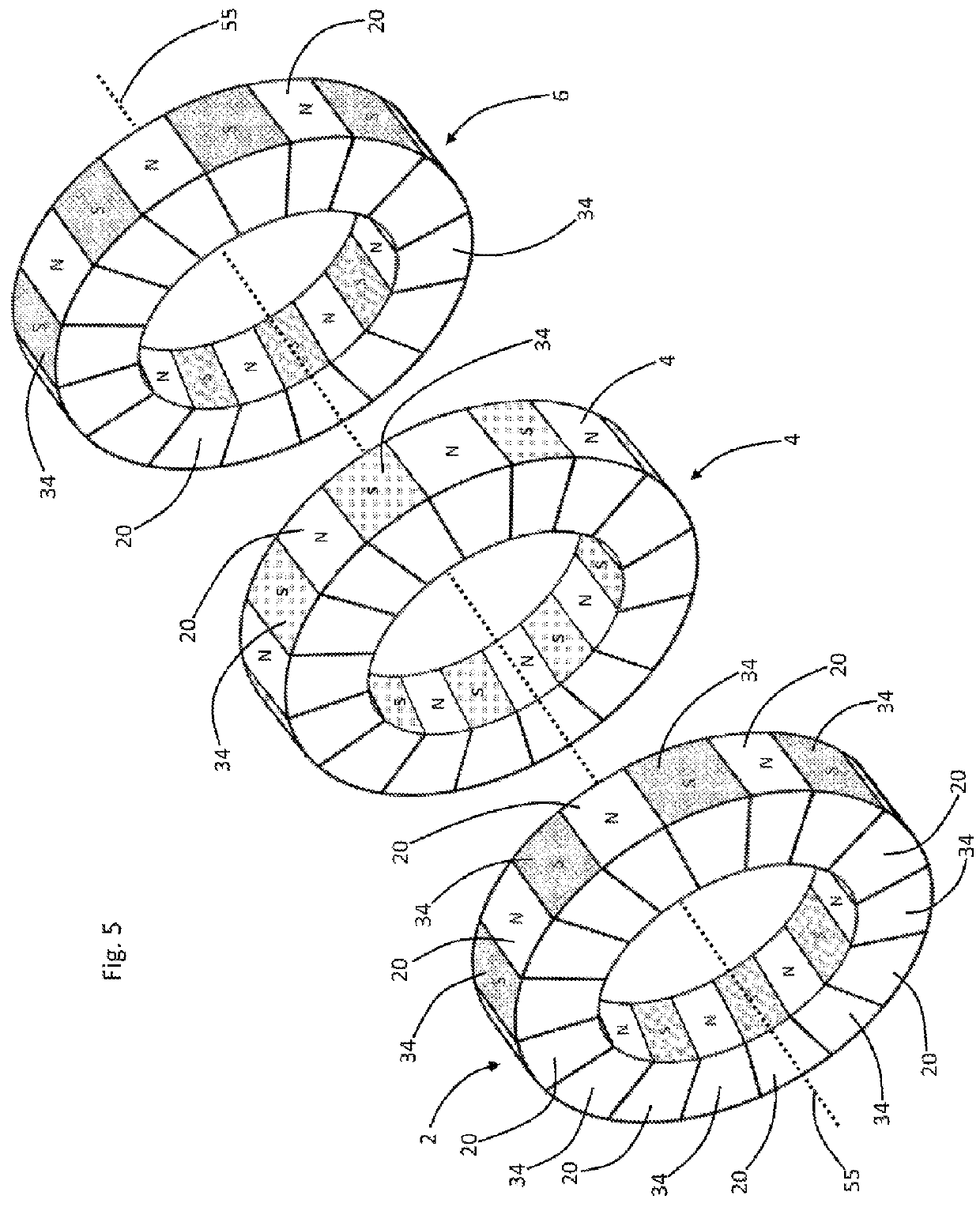
[0024]Referring now to the drawings and in particular simultaneously to Drawing FIGS. 1, 2, and 6, a preferred embodiment of the instant inventive magnetic roll is referred to generally by Reference Arrow 1. A permanent magnet segment component of the roll 1 is referred to generally by Reference Arrows 20, such magnet 20 having a convexly arcuately curved radially outer face or end 22, and a concavely arcuately curved radially inner face or end 24. The magnet 20 has an axial end 26, an oppositely axial end 28, a circumferential end 30, and a counter-circumferential end 32. The magnetic characteristics of the magnet 20 include a radially extending polar axis 21 whose north direction is toward the magnet's radially outer end 22, the south direction being toward the radially inner end 24.

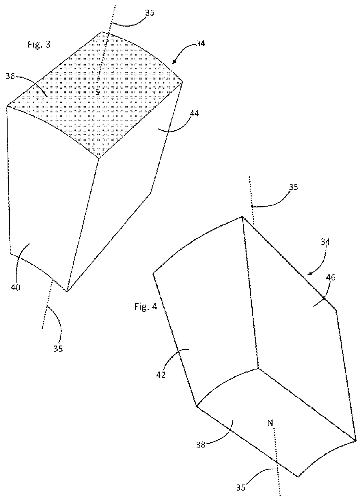
[0025]Referring simultaneously to FIGS. 3 and 4, a similarly geometrically configured permanent magnet having an opposite magnetic characteristic is referred to generally by Reference Arrows 34. The ma...


PUM


Abstract

A magnetic roll having a rotation axis, the magnetic roll including an axial series of segmented rings, each of the rings' segments incorporating a permanent having an outer end, an inner end, an axial end, an oppositely axial end, a circumferential end, a counter-circumferential end, a north pole positioned at the inner or outer end, and a south pole positioned oppositely from the north pole; a bonding matrix rigidly interconnecting the rings; and a magnetic armature operatively spanning between the permanent magnets' inner ends.

Description

FIELD OF THE INVENTION[0001]This invention relates to roll or roller configured magnets which are utilized in conveyor belt actuated magnetic separators.BACKGROUND OF THE INVENTION[0002]Continuous loop belt conveyors having an output end roller are known to be adapted for separation of ferrous materials conveyed by the conveyor. Such adaptation magnetizes the cylindrical outer surface of the conveyor's output end roller.[0003]As a beneficial result of such conveyor output roller, magnetization, non-ferrous items such as plastics which are forwardly carried along the conveyor's upper flight may dispense at the conveyor's conventional output, while ferrous items, such as intermixed scrap nails and screws may separately dispense from the conveyor's lower flight upon rearwardly exiting the roller's magnetic field.[0004]Where materials to be separated by such conveyor belt magnetic separators are magnetically permeable or have a high level of magnetic susceptibility, conventional and kno...

Claims


Application Information

Patent Timeline
Patent Type & Authority Patents(United States)
IPC IPC(8): B03C1/10B03C1/18B03C1/033B03C1/034
CPCB03C1/18B03C1/0332B03C1/034B03C1/12B03C1/247H01F7/0268B03C2201/22
Inventor SUDERMAN, DONALD A.
Owner BUNTING MAGNETICS
Why Eureka
Try Eureka