Analysis device and analysis method

a biomolecule and analysis device technology, applied in the field of biomolecule analysis methods, can solve the problems of difficult detection of these markers and small amount of cancer markers, and achieve the effects of improving quantitativity, preventing the engulfment of fluorescent dyes, and performing easily

Active Publication Date: 2018-05-08
HITACHI HIGH-TECH CORP
View PDF22 Cites 4 Cited by
  • Summary
  • Abstract
  • Description
  • Claims
  • Application Information

AI Technical Summary

Benefits of technology

[0007]According to the present invention, the majority of magnetic particulates in the liquid can be attracted to the surface of the support base, and held by the adhesive layer. Further, by turning off the magnetic field, the aggregation among the magnetic particulates can be resolved, and the magnetic particulate layer on the supporting substrate can be made single-layered. By making the magnetic particulate layer single-layered, focusing to the fluorescent dyes on the support base can be performed easily, and by preventing the engulfment of fluorescent dyes due to the aggregation of the magnetic particulates, quantitativity is improved. Since the capture rate of biomolecules, which are the analysis object, can be improved significantly by the biomolecule analysis using the present invention, detection with higher sensitivity than in the prior art is possible. Further, because the device having a complex structure is not required, it is very simple in comparison with the prior art and a significant improvement of throughput can be obtained by combining with the automatic control unit.

Problems solved by technology

In the early stage cancer, the amount of these cancer markers is small and difficult to detect these markers; it is the same situation when there exists the cancer marker of originally low expression level.

Method used


Image

  • Analysis device and analysis method
  • Analysis device and analysis method
  • Analysis device and analysis method

Examples


example 1

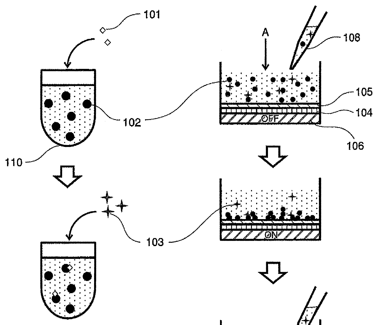
[0023]One example of the analysis method and the configuration of the device of the present Example are explained with reference to FIG. 1. In the beginning, biomolecules to be detected are captured by magnetic particulates in advance, and further labeled with fluorescent labels. All of these reactions are carried out under a normal temperature in a buffer solution, and either one of the reaction of magnetic particulates with biomolecules and the reaction of fluorescence labelling substances with biomolecules may be carried out first, or may be carried out at the same time. The preparation method of magnetic particulates to capture and the method of fluorescence labeling will be described in detail in Examples 3 and 4.

[0024]In the present Example, the reaction method is explained with reference to FIG. 1 by taking as an example a method that the biomolecules to be detected are antigens 101, antigens 101 are captured by antibody-bound magnetic particulates 102, and further they are l...

example 2

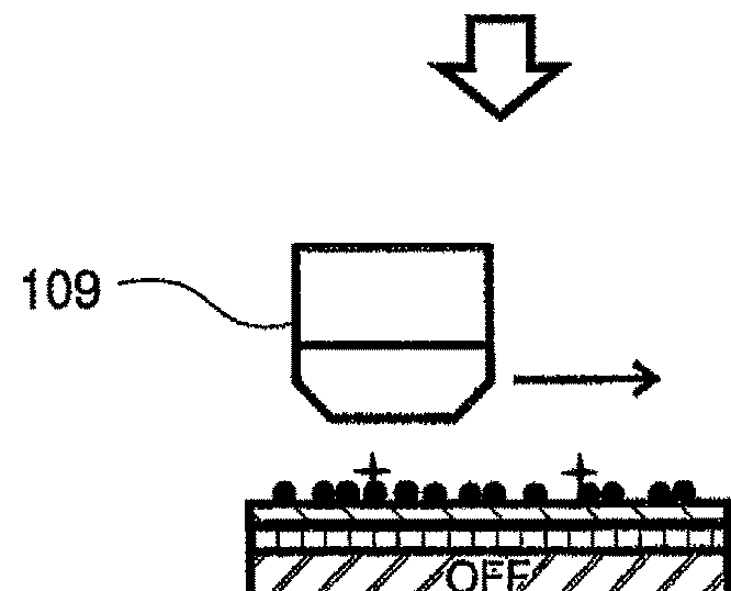
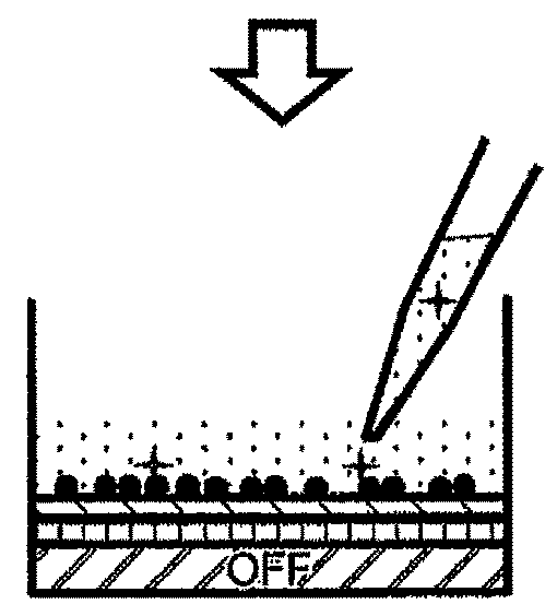
[0027]Next, a configuration of a device for fluorescence detection in combination with a flow channel is explained with reference to FIG. 2. In the same manner as in Example 1, the present device has a smooth supporting substrate 203 for presenting magnetic particulates 201 in two-dimension, and an adhesive layer 204 for immobilizing the magnetic particulates 201 on the surface of the supporting substrate 203 and a magnetic field generator 205 which is capable of switching the on / off or the intensity levels of the magnetic field for attracting the magnetic particulates 201 to the adhesive layer 204 just below the supporting substrate 203 are installed. Further, in all the directions of the supporting substrate 203, side walls 206 are installed, and further covered thereon with a smooth transparent cover member 207. For example, PDMS (polydimethylsiloxane) may be used as the material of the side wall 206, and the quartz can be used for the material of the cover member 207. Tubes 208 ...

example 3

[0029]Next, a configuration of a device having a function of changing reversibly the adhesive force of an adhesive layer 304 is explained with reference to FIG. 3. In the same manner as in Example 2, the present device has a smooth supporting substrate 303 for presenting magnetic particulates 302 in two-dimension, and the adhesive layer 304 for immobilizing the magnetic particulates 302 on the surface of the supporting substrate 303 and a magnetic field generator 305 which is capable of switching the on / off or the intensity levels of the magnetic field to attract the magnetic particulates 302 to the adhesive layer 304 just below the supporting substrate 303 are installed. Further, in all the directions of the supporting substrate 303, side walls 306 are installed, and further covered thereon with a smooth transparent cover member 307. Tubes for inserting and removing a solution are mounted at two places of the side walls 306. The magnetic field generator 305 for attracting the magne...


PUM

PropertyMeasurementUnit
magnetic fieldaaaaaaaaaa
diametersaaaaaaaaaa
diametersaaaaaaaaaa

Abstract

Biomolecules are specifically captured with magnetic particles and the biomolecules are labeled with fluorescence. A magnetic field generator, for attracting the magnetic particles to the support substrate, is provided on the reverse face of the support substrate, and an adhesion layer is provided on the surface of the support substrate to hold the magnetic particles. First, a dispersing solution for the magnetic particles is placed on the surface of the support substrate with the magnetic field in an off state. Next, the magnetic field is turned on, and the magnetic particles in solution are attracted to the support substrate surface. The magnetic particles colliding with the support substrate adhere to the adhesion layer of the support substrate surface, and then the magnetic field is turned off. Thus, aggregations can be broken up while the magnetic particles are held, and a magnetic particle layer on the support substrate can be a single layer.

Description

TECHNICAL FIELD[0001]The present invention relates to a biomolecule analysis method using magnetic particulates and a biomolecule analyzer.BACKGROUND ART[0002]In recent years, in the field of cancer diagnosis, various cancer markers have been investigated in order to know a sign of cancer onset in an early stage, and practical applications is progressing. The cancer marker is a secretory biological factor derived from cancer cells, and increases with the progression of the cancer and appears in blood and / or urine. For example, proteins such as hormones and cytokines, and nucleic acid such as micro-RNA are known. In the early stage cancer, the amount of these cancer markers is small and difficult to detect these markers; it is the same situation when there exists the cancer marker of originally low expression level. At present, the mainstream of the high sensitive method for detecting the cancer markers is in the immunoassay method using an antibody, and the techniques such as the EL...

Claims


Application Information

Patent Timeline
Patent Type & Authority Patents(United States)
IPC IPC(8): G01N21/64G01N33/543C12Q1/68
CPCG01N33/54333C12Q1/6834G01N21/6428G01N21/6489G01N33/54326G01N33/54346G01N21/6458G01N2021/6441
Inventor HAMASAKI, KOSHINSAITO, TOSHIRO
Owner HITACHI HIGH-TECH CORP
Why Eureka
Try Eureka