Supercharge Your Innovation With Domain-Expert AI Agents!

Electrospray emitter and method of manufacture

a technology of electrospray emitter and emitter, which is applied in the field of electrospray, can solve the problems that the electrospray device based on capillaries is difficult to manufacture, handle and clean, or to manufacture in large numbers, and achieves the effect of reducing electrical breakdown

Active Publication Date: 2018-05-15
QUEEN MARY UNIV OF LONDON
View PDF28 Cites 0 Cited by
  • Summary
  • Abstract
  • Description
  • Claims
  • Application Information

AI Technical Summary

Benefits of technology

The patent describes a device that controls the emission of electrospray. The device has a control electrode that is located near the channel where the electrospray is emitted. This makes the device easier to clean and more robust. The device can be a flat or curved sheet with no protrusions or nozzles on its surface. The aperture through which the electrospray is emitted can be located on the same surface as the sheet or recessed. The method of construction is simplified by allowing the channel and groove to be made during the same manufacturing step.

Problems solved by technology

However, electrospray devices based on capillaries may be difficult to manufacture, handle and clean or to manufacture in large numbers.

Method used


Image

  • Electrospray emitter and method of manufacture
  • Electrospray emitter and method of manufacture
  • Electrospray emitter and method of manufacture

Examples


Embodiment Construction

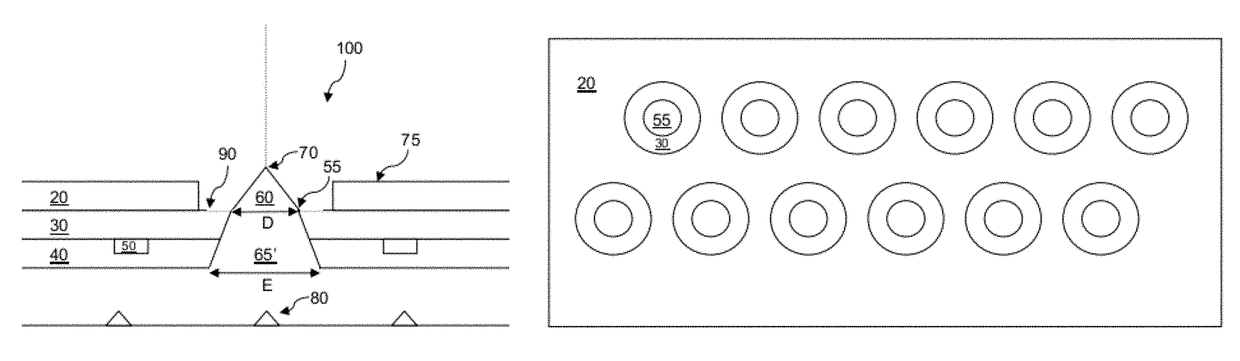
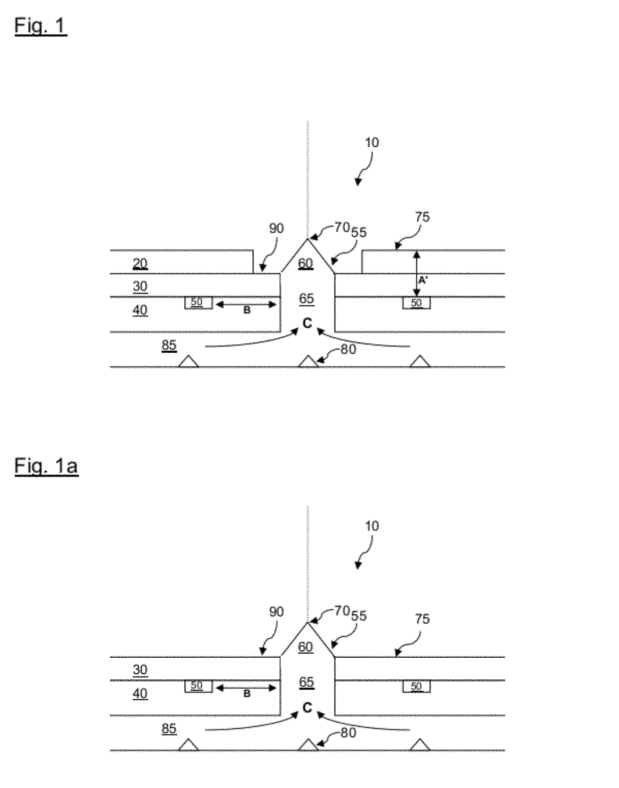
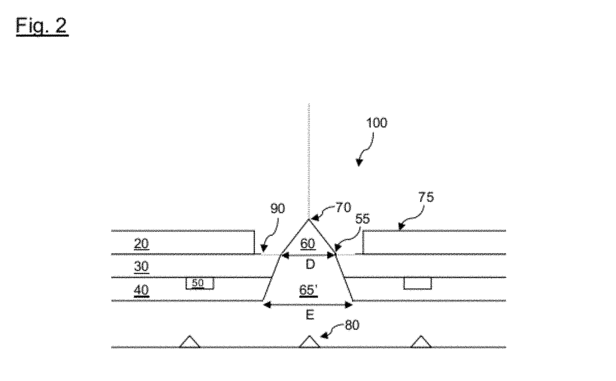
[0068]FIG. 1 shows a schematic diagram in cross-section of an electrospray emitter 10. A single electrospray emitter 10 is shown although there may be many electrospray emitters formed on a single device. A liquid conduit 85 supplies liquid to be emitted into a channel 65, as shown by arrows C. The liquid conduit 85 may supply a single electrospray emitter 10, as shown in FIG. 1 or the liquid conduit 85 may supply many separate electrospray emitters 10 in communication with a the single liquid conduit 85. Furthermore, several separate liquid conduits 85 may be arranged to supply different liquid types to one or more electrospray emitters 10 on a single device.

[0069]An electric charge may be applied to the liquid by charging electrodes 80. These charging electrodes 80 may extend into the liquid conduit 85 or placed at another suitable location and they may be of various shapes such as conical, for instance. The charging electrodes 80 may be on one or any of the faces of the material ...


PUM


Abstract

An electrospray emitter (10) for emitting a liquid comprising a sheet (40) having a channel (65) opening to an aperture (55) on a flat emitter surface extending across the sheet (40). A charging electrode (80) coupleable to an electrical supply and arranged to apply an electrical charge to liquid passing into the channel (65). A control electrode (50) proximal to the channel (65) for controlling electrospray emission, that may be embedded in the sheet. A non-wetting or insulating layer (30) may be applied to the sheet.

Description

FIELD OF THE INVENTION[0001]The present invention relates to electrospraying and in particular an electrospray emitter and an array of electrospray emitters.BACKGROUND OF THE INVENTION[0002]Electrospray occurs when the electrostatic force on the surface of a liquid overcomes surface tension. Under certain conditions, a Taylor cone is created at the emitter of an electrospray device. A liquid jet may be emitted from the apex of the Taylor cone.[0003]Electrospray devices may be formed from glass or metal capillaries fed by a reservoir. Such devices are described in WO2007 / 066122. However, electrospray devices based on capillaries may be difficult to manufacture, handle and clean or to manufacture in large numbers.[0004]Therefore, there is required an electrospray emitter that overcomes these problems.SUMMARY OF THE INVENTION[0005]In accordance with a first aspect of the present invention there is provided an electrospray emitter for emitting a liquid comprising:[0006]a sheet having a ...

Claims


Application Information

Patent Timeline
Patent Type & Authority Patents(United States)
IPC IPC(8): B05B5/025B41J2/06B05B5/053B05B1/14
CPCB41J2/06B05B5/0255B05B5/0533B41J2002/061B05B1/14B05B5/025B41J2/16
Inventor STARK, JOHNSHEPHERD, MARK RICHARD
Owner QUEEN MARY UNIV OF LONDON
Features
  • R&D
  • Intellectual Property
  • Life Sciences
  • Materials
  • Tech Scout
  • Unparalleled Data Quality
  • Higher Quality Content
  • 60% Fewer Hallucinations
Learn More