
Communication device and system for performing data communication using a human or animal body as transmission medium

a technology of communication device and data communication, which is applied in the direction of instruments, power management, climate sustainability, etc., can solve the problems of impossible or impractical propagation of one and the same type of signals, and achieve the effects of preventing the buildup of dc components, improving the signal-to-noise ratio (snr), and low noise amplifiers

Inactive Publication Date: 2018-05-15
KONINKLJIJKE PHILIPS NV
View PDF15 Cites 0 Cited by
  • Summary
  • Abstract
  • Description
  • Claims
  • Application Information

AI Technical Summary

Benefits of technology

[0009]By sharing the transceiver unit between the both types of transducers, efficient power consumption can be obtained whilst at the same time allowing an elegant and more simple design (only one transceiver is needed to operate both transducers). The simplified design enables the communication device to be produced at low cost, thereby increasing its usability in all kinds of appliances. Moreover, the device can be smaller, which further increases it's usability.
[0010]The ultrasonic communication offers the best signal propagation for smallest form factor and energy consumption inside the body, while body-coupled communication is very power efficient and user-friendly for on-body and touch communication. At the edge of two different mediums (body surface and body interior) the properties of the communication channel change dramatically (e.g. from water to air). Conventionally, this makes the propagation of one and the same type of signal impossible or impractical. However, in the present design use is made of transducers that convert the electric signals into signals that propagate optimally in the designated medium, e.g. ultrasonic for in-body and electrostatic for on-body.
[0011]In particular, in accordance with the present invention, the ultrasonic and electrostatic transducers applied are of capacitive type and therefore have similar properties in terms of operation frequency and signal type. The transducers can therefore be operated via the same transceiver, thereby allowing a design wherein the transceiver unit is shared. For both the electrostatic transducer (e.g. of body coupled communication type) and the ultrasonic transducer, the same communication protocols can be applied. This enables to build a unified communication network that goes in and out of body based on the communication device of the present invention. Communication may therefore be performed faster and more efficient, and because of the integration of both types of transducers into one device with a (at least one) shared transceiver the area of application of the technology is increased. The need for only a single transceiver, i.e. in a half duplex embodiment, for example provides an important size reduction compared to an implementation relying on two different transceivers (one for each type of signal and associated protocols). Hence, both technologies are easily integrated into a single device (e.g. a wearable user device or a medical appliance) as a result of the present invention.
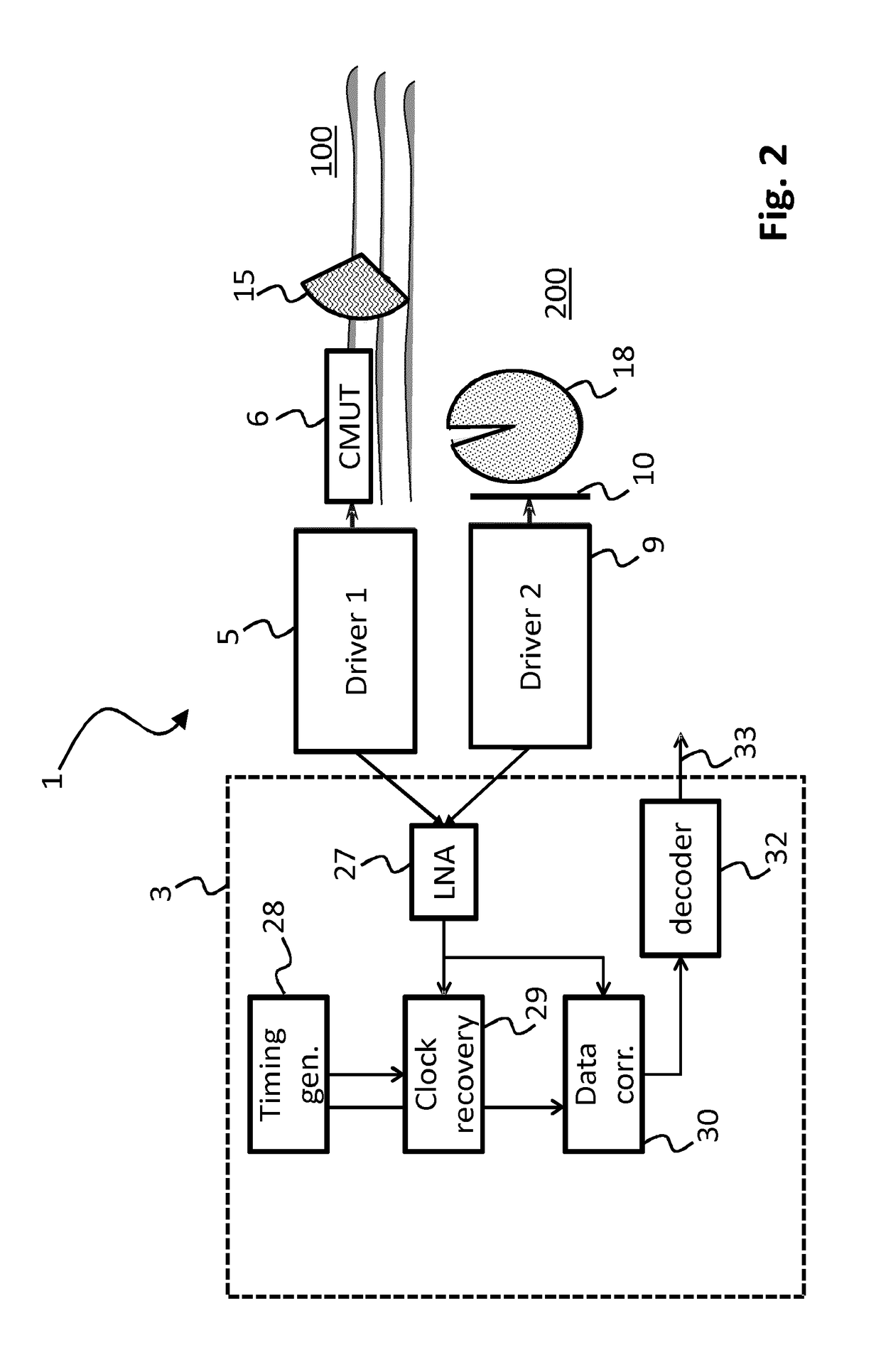
[0019]The receiver unit in the transceiver of the communication device may further comprise a low noise amplifier to account for the low peak-peak voltage in the received signal of the CMUT and the electrostatic capacitive coupler. In particular for the CMUT the received signal will typically be a few tens of mV peak-peak (e.g. 10-90 mV), and a low noise amplifier may be advantageous for improving the signal-to-noise ratio (SNR). Timing generator, clock recovery, data correlation and decoding, as well as the optional use of a low noise amplifier as indicated in the present embodiment, may be shared and integrated in the shared transceiver electronics.

Problems solved by technology

Conventionally, this makes the propagation of one and the same type of signal impossible or impractical.

Method used


Image

  • Communication device and system for performing data communication using a human or animal body as transmission medium
  • Communication device and system for performing data communication using a human or animal body as transmission medium
  • Communication device and system for performing data communication using a human or animal body as transmission medium

Examples


Embodiment Construction

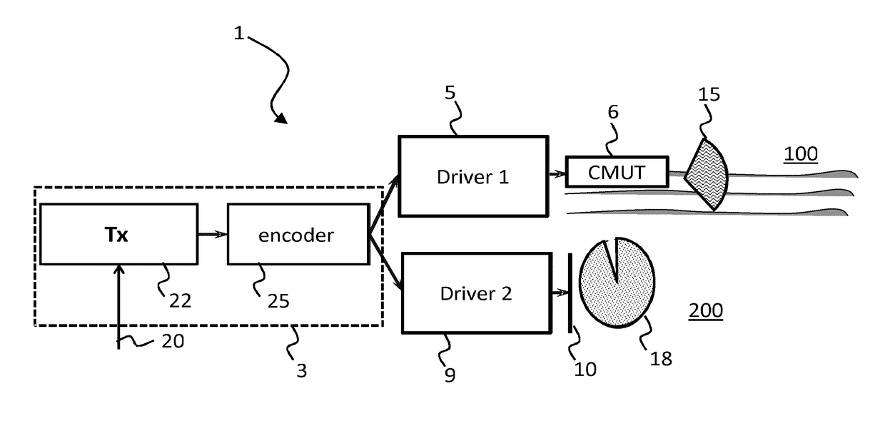
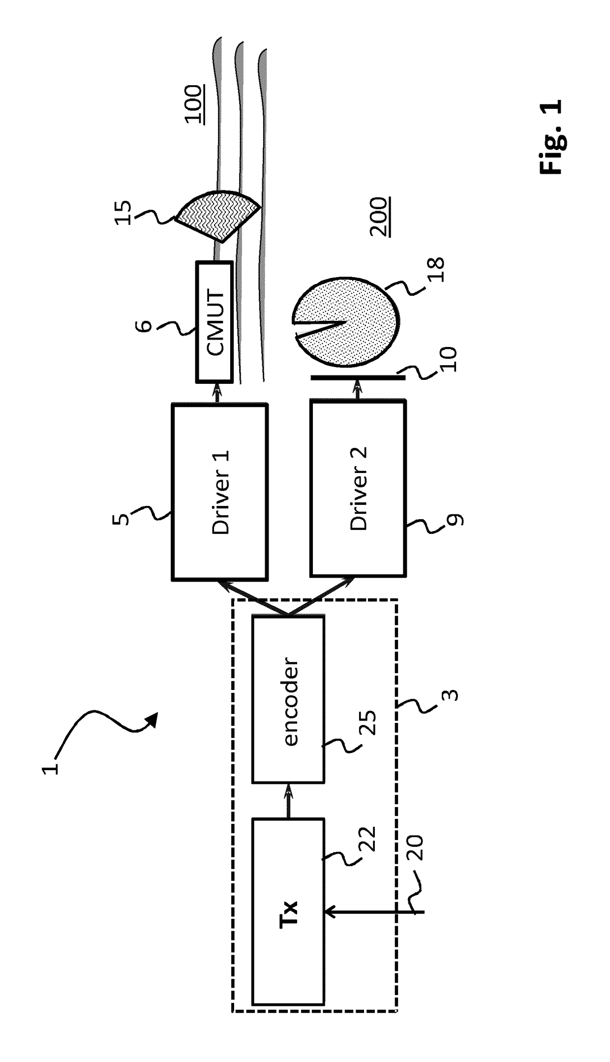
[0034]FIGS. 1 and 2 illustrate a communication device of the present invention, in particular a possible layout for transmission of signals (FIG. 1) and for receipt of signals (FIG. 2). FIG. 1 provides a block diagram which describes the main components of the transmitting side of a dual-modality communication system 1 of the present invention. Transmitter 22 may receive control signals via the input 20 of the transceiver unit 3, and may generate data for transmission in response to such control signals. The data generated by the transmitter logic 22 is first encoded by the data encoder 25. The encoder 25 for example may use Manchester encoding in order to address the capacitive nature of the transducers 6 and 10. However, another type of DC free encoding could also be used instead. The encoded transmission signal is provided to two modality specific driver blocks 5 and 9 that incorporate driver electronics and proper bias and impedance matching networks. The transducer 6 is a capac...


PUM


Abstract

The invention is directed at a communication device for performing data communication using a human or animal body as transmission medium. The communication device comprises a transceiver unit comprising at least one of a transmitter and a receiver. The communication device also comprises an electrostatic transducer for enabling data communication via a surface of the body with one or more user devices in touch with or located near (i.e. in close proximity, e.g. within a range of 0-10 mm therefrom) the body. The communication device further comprises an ultrasonic transducer for enabling data communication through the body using ultrasonic waves. Both the electrostatic transducer and the ultrasonic transducer are capacitive type transducers connected to and operated via the transceiver unit.

Description

FIELD OF THE INVENTION[0001]The present invention is directed at a communication device for performing data communication using a human or animal body as transmission medium, the communication device comprising a transceiver unit comprising at least one of a transmitter and a receiver, and wherein the communication device comprises an electrostatic transducer for enabling data communication via a surface of the body with one or more user devices in touch with or near the body. The invention is further directed at a system of communications devices arranged for intercommunication between said communication devices via data communication using a human or animal body as transmission medium.BACKGROUND[0002]With the increasing number and functionality of implantable and wearable devices, the need increases for a reliable high-throughput and safe communication in and around the body. There are several technological options that can serve this need, and their suitability is judged by the p...

Claims


Application Information

Patent Timeline
Patent Type & Authority Patents(United States)
IPC IPC(8): H04B13/00G06F13/40H04B1/38H04B1/3827H04W52/52
CPCH04B13/005H04B1/385G06F13/4072H04W52/52Y02D10/00
Inventor OUZOUNOV, SOTIR FILIPOV
Owner KONINKLJIJKE PHILIPS NV
Learn More