Machine tool

a technology of machine tools and cutting tools, applied in the field of machine tools, can solve the problems of uneven machining quality of workpieces, uneven quality of workpieces, and remarkable wear of cutting edges of cutting tools

Active Publication Date: 2018-05-22
CITIZEN WATCH CO LTD
View PDF11 Cites 10 Cited by
  • Summary
  • Abstract
  • Description
  • Claims
  • Application Information

AI Technical Summary

Benefits of technology

[0008]Accordingly, in view of the foregoing problems, the present invention aims to provide a machine tool capable of making machining quality of workpieces mainly composed of difficult-to-cut materials stable at a high level and also capable of inhibiting the occurrence of a fire, and yet, being practical and having no restrictions on machining shape of workpieces, and furthermore being capable of realizing low-frequency vibration cutting which allows chips to be fragmented finely even if the cutting tool and / or the workpiece is vibrated at low frequency on multiple axes.
[0016]In the machine tool according to an embodiment of the invention, the movement of the cutting tool holding means (the cutting tool holder 5 and the rotation mechanism 31) or the workpiece holding means (the rotation mechanism 3 and the workpiece chuck mechanism 32) is controlled by the control mechanism (the control device 8) so as to relatively synchronize the workpiece (2) and the cutting tool (4) in multiple axial directions and vibrate them at a low frequency. As a result, cavitation is generated in a space (K) (see FIG. 1 etc.) appearing between the workpiece (2) and the cutting tool (4), into which a coolant etc., used at the time of performing the cutting is sucked. Therefore, cutting heat and frictional heat generated at the time of machining the workpiece (2) can be cooled and lubricated effectively. Thus, according to the present invention, machining quality of workpieces can be stabilized.
[0017]Further, according to the present invention, chips of the workpiece (2) become powdered by the low-frequency vibration at the time of cutting the workpiece (2) by the cutting tool (4), and this makes it difficult for the chips to catch on the cutting tool. Consequently, the quality can be stabilized and furthermore the occurrence of a fire can be suppressed.
[0019]According to an embodiment of the invention, the movement of the cutting tool holding means (the cutting tool holder 5 and the rotation mechanism 31) or the workpiece holding means (the rotation mechanism 3 and the workpiece chuck mechanism 32) is controlled by the control mechanism (the control device 8), and when the workpiece (2) and the cutting tool (4) are fed relative to each other in multiple axial directions, the workpiece (2) and the cutting tool (4) are fed synchronously and vibrated at a low frequency. As a result, the low-frequency vibration cutting capable of finely fragmenting chips can be realized.
[0020]Further, in the machine tools as above, the cutting tool holding means (the cutting tool holder 5 and the rotation mechanism 31) can be provided movably in multiple axial directions. Further, the workpiece holding means (the rotation mechanism 3 and the workpiece chuck mechanism 32) can be provided movably in multiple axial directions. Furthermore, the cutting tool holding means (the cutting tool holder 5) and the workpiece holding means (the rotation mechanism 3) can be provided movably so that the cutting tool holding means (the cutting tool holder 5) and the workpiece holding means (the rotation mechanism 3) can cooperatively move to feed the cutting tool (4) relative to the workpiece (2) in multiple axial directions as in the machine tool according to the invention.
[0021]On the other hand, as in the machine tools according to the invention, the provision of the vibration cutting information storing means (the vibration cutting information storing portion 83) in which data for vibrating the workpiece (2) and the cutting tool (4) at a low frequency in the above manner is prestored allows the control mechanism (the control device 8) to exercise control based on the data stored in the vibration cutting information storing means (the vibration cutting information storing portion 83). Consequently, the low-frequency vibration cutting with optimum vibration capable of finely fragmenting chips can be achieved. More specifically, the frequency is determined by the amplitude and the interpolation speed thereof in theory. Practically, however, the relationship between the amplitude or the interpolation speed thereof and the frequency varies variously depending on mechanical characteristics (for example, theoretical mass, motor characteristics, etc.) of the machine tool, and is not a fixed relationship such as proportional relation. Thus, desired vibration (optimum frequency and amplitude) cannot be generated by theoretical calculations. Further, if the low-frequency vibration cutting is attempted to be realized with the aim of fragmenting chips, the number of revolutions of the workpiece or the number of revolutions of the cutting tool and a cycle at the time of performing the low-frequency vibration cutting need to be set so as not to be synchronized. However, it is extremely difficult to work out such a cycle by calculation. Therefore, if data for vibrating the workpiece (2) and the cutting tool (4) at low frequency in the above manner is prestored in the vibration cutting information storing means (the vibration cutting information storing portion 83) and the control mechanism (the control device 8) is made to exercise control based on the data, the low-frequency vibration cutting can be realized with optimum vibration capable of finely fragmenting chips.

Problems solved by technology

There is a problem that cutting heat and frictional heat generated at that time cannot be cooled and lubricated effectively, which causes a cutting edge of the cutting tool to be remarkably worn out and then machining quality of workpieces to be uneven.
In addition, there is also a problem that chips generated at the time of cutting get caught on the cutting tool, which causes not only unevenness in the quality but also the occurrence of fire.
On the other hand, the machine tool performing the ultrasonic vibration cutting has an advantage of allowing cutting of difficult-to-cut materials, but takes significant machining time and additionally is very expensive.
Moreover, there is a problem that tooling installation sites having a role as an adapter for attaching the cutting tool to the machine tool are restricted due to use of the piezoelectric element.
Therefore, there is a problem that the machine tool performing the ultrasonic vibration cutting disadvantageously lacks practical use.
In addition, the machine tool having the vibration exciter attached to the cutting tool has a problem that the machining shape of workpieces is limited.
Therefore, the rotation in the direction of arrow P10 is physically impossible.
As a result, the machine tool having the vibration exciter attached to the cutting tool has the problem that the machining shape of workpieces is limited.

Method used


Image

  • Machine tool
  • Machine tool
  • Machine tool

Examples


example 1

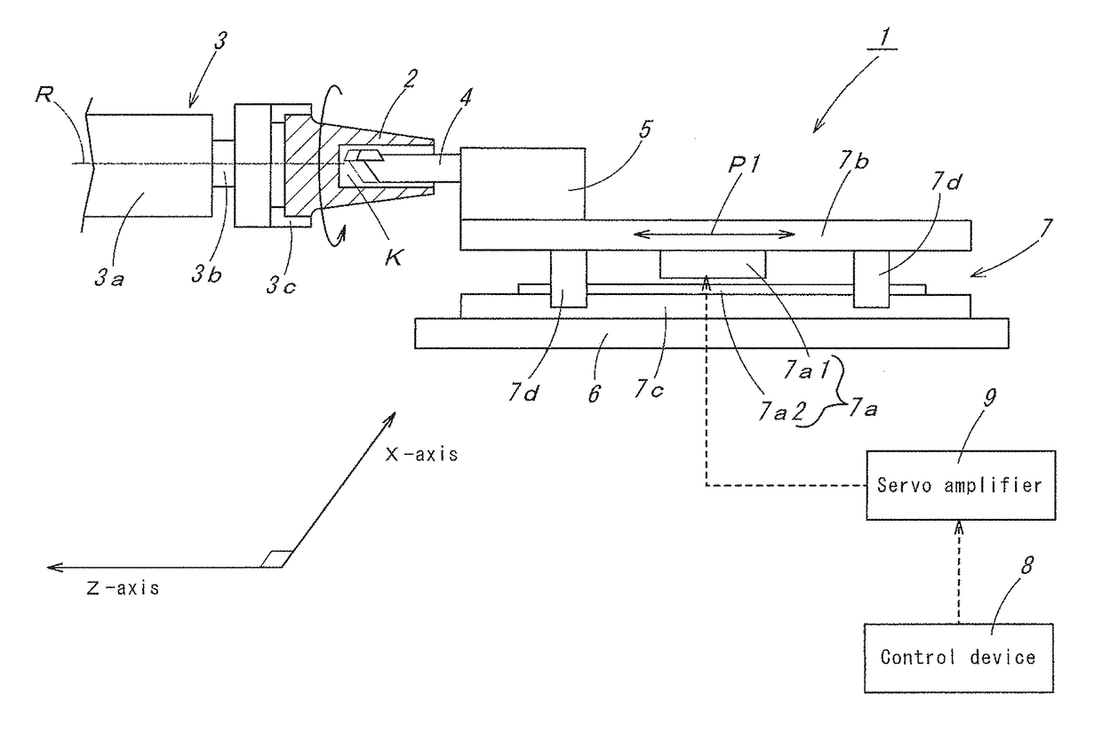
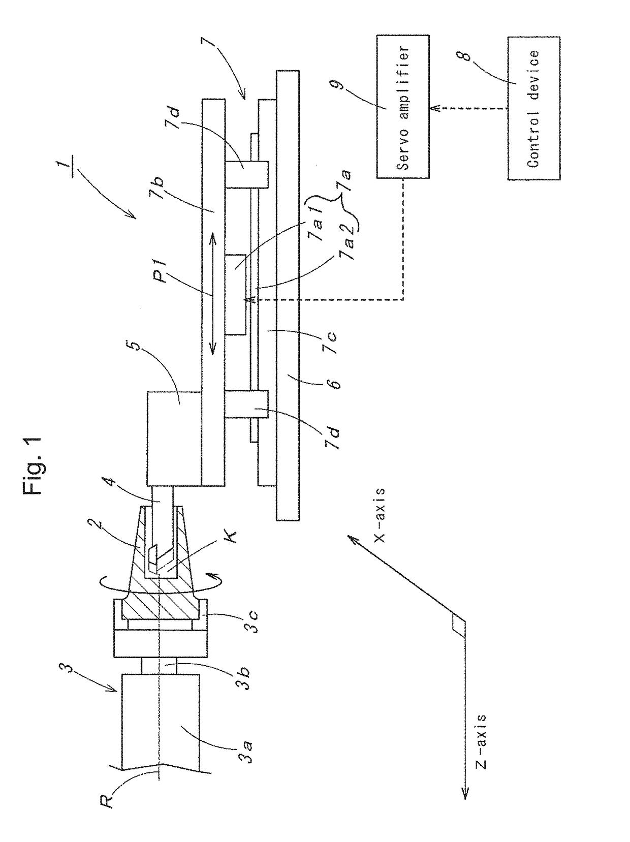
[0110]As a first example, the machine tool 20 according to the third embodiment was used to perform the machining of a workpiece 2. An automatic lathe L16CNC manufactured by CITIZEN MACHINERY CO., LTD. was used as the machine tool 20. A bar SKD11-φ12.0 was used as the workpiece 2, and a turning tool with a diameter of 12 mm was used as the cutting tool 4. Further, a combination of a ball screw and a servomotor was used as the cutting tool feeding mechanism 7. The number of revolutions of the workpiece 2 was programmed at 600 rpm, and feeds of the cutting tool 4 and the workpiece 2 per revolution of the workpiece 2 were each programmed at 0.01 mm, and then the cutting of the workpiece 2 was performed. As a consequence, a machined workpiece shown in FIG. 11 could be produced. It is noted that the amplitude of low-frequency vibration of the cutting tool 4 and the workpiece 2 according to the foregoing programmed values was each set at 0.03 and the frequency was each set at 9 Hz.

[0111]O...

example 2

[0113]Next, as a second example, the machine tool 1 according to the first embodiment was used to machine a workpiece 2 by the low-frequency vibration cutting in order to produce a machined workpiece shown in FIG. 12. A CNC lathe NL-10 manufactured by CITIZEN MACHINERY CO., LTD. was used as the machine tool 1. A bar φ10-SUS304 was used as the workpiece 2, and DCGT11T304ER-U-PR930 manufactured by KYOCERA Corporation was used as the cutting tool 4. Further, a linear servomotor manufactured by Mitsubishi Electric Corporation was used as the cutting tool feeding mechanism 7. The number of revolutions of the workpiece 2 was programmed at 3750 rpm, and the feed of the cutting tool 4 per revolution of the workpiece 2 was programmed at 0.01 mm, and SUNCUT EF-5N (water-insoluble) manufactured by NIPPON GREASE CO., LTD. was used as the coolant. Further, the amplitude of low-frequency vibration of the cutting tool 4 according to the foregoing programmed values was set at 0.03 and the frequency...


PUM

PropertyMeasurementUnit
frequencyaaaaaaaaaa
vibration frequenciesaaaaaaaaaa
vibration frequencyaaaaaaaaaa

Abstract

A machine tool for machining a workpiece is provided with a cutting tool holder for holding a cutting tool and a rotation mechanism for holding the workpiece. One or both of the cutting tool holder and the rotation mechanism are movable on multiple axes so that the cutting tool is movable relative to the workpiece in multiple axial directions. A control device is provided for controlling the movement of one or both of the cutting tool holder and the rotation mechanism to synchronously vibrate the workpiece and the cutting tool relative to each other at a low frequency in multiple axial directions.

Description

FIELD OF THE INVENTION[0001]The present invention relates to machine tools which rotate a cutting tool or a workpiece and perform cutting of the workpiece.BACKGROUND OF THE INVENTION[0002]In conventional machine tools, a cutting tool, such as a turning tool, moves relative to a workpiece in a fixed direction to cut the workpiece. On the other hand, there is known a machine tool which performs so-called ultrasonic vibration cutting, which uses a piezoelectric element at a cutting edge of a cutting tool and cuts a workpiece while applying vibration in an ultrasonic range (for example, as disclosed in Japanese Published Unexamined Patent Application No. 2000-052101). Further, there is known a machine tool in which a vibration exciter is attached to a cutting tool, as disclosed in Japanese Published Examined Patent Application No. S49-17790, which will be described with reference to FIG. 13. The machine tool 100, depicted in FIG. 13, has a first guideway 101. This first guideway 101 gui...

Claims


Application Information

Patent Timeline
Patent Type & Authority Patents(United States)
IPC IPC(8): B23Q1/00B23B27/22G05B19/404B23B29/12B23Q1/34B23Q5/22G05B19/4093B23Q5/28
CPCB23Q1/34B23B27/22B23B29/125B23Q5/22B23Q5/28G05B19/40937G05B19/404Y10T82/2502B23Q2230/004G05B2219/45136Y02P90/265Y10T82/25Y02P90/02B23B1/00B23Q15/013G05B19/4093
Inventor HARIKI, RYOKOBAYASHI, KOUICHIIMASAKI, NOBUYOSHI
Owner CITIZEN WATCH CO LTD
Why Eureka
Try Eureka