
Method for optimizing utilization of programmable logic elements in control units for vehicles

a technology of programmable logic and electronic control unit, which is applied in the direction of electric programme control, process and machine control, instruments, etc., can solve the problems of low complexity, decreased flexibility of the application of the system to be tested, and increased cost of test equipment and test execution, so as to achieve free computing capacity, improve utilization rate, and improve the effect of efficiency

Active Publication Date: 2018-05-22
DSPACE DIGITAL SIGNAL PROCESSING & CONTROL ENG
View PDF11 Cites 2 Cited by
  • Summary
  • Abstract
  • Description
  • Claims
  • Application Information

AI Technical Summary

Benefits of technology

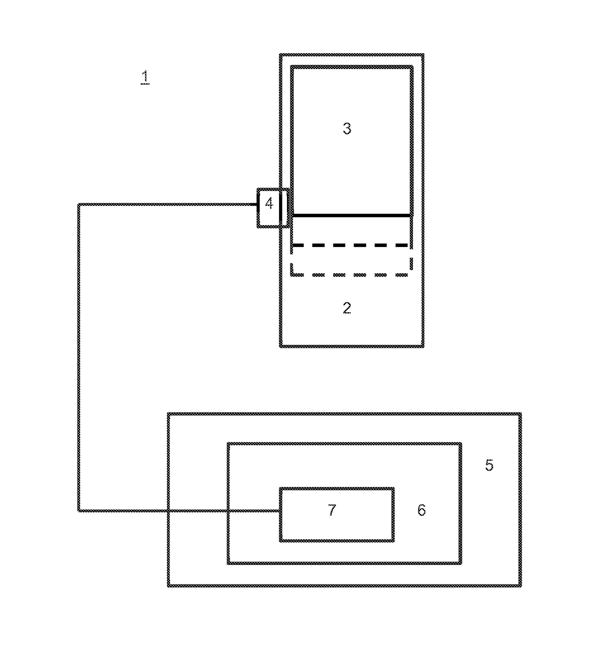
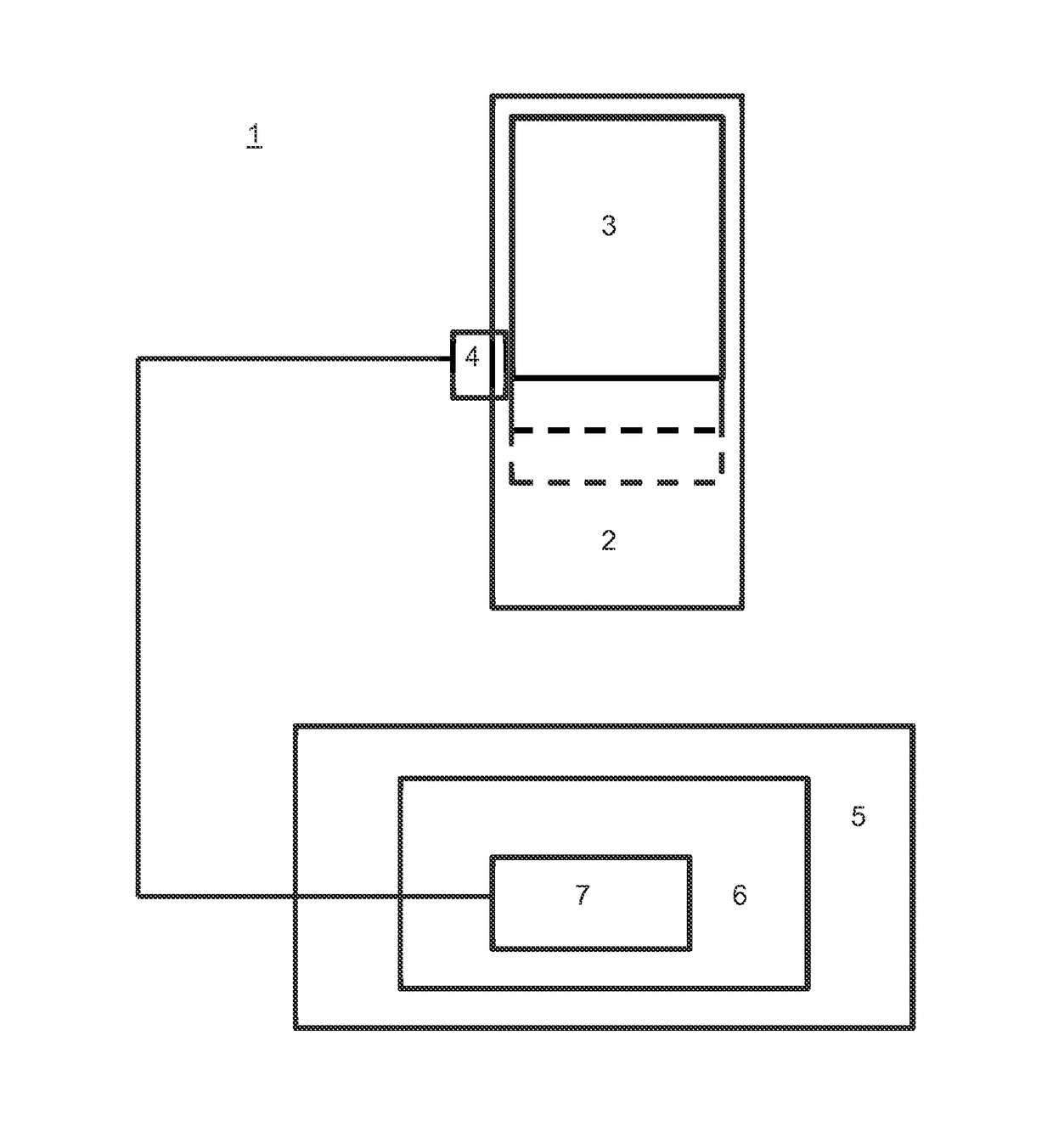
The present invention provides a way to efficiently use a soft CPU, which is a programmable logic element, by obtaining precise profiling data through processor-in-the-loop simulations of the soft CPU. This allows for the soft CPU to be configured based on the available area on the programmable logic element and the functions of the program code to be executed by the soft CPU. Additionally, the invention allows for optimal utilization of the soft CPU and the remaining area on the programmable logic element through suitable configuration of the model of the control unit via programs such as TargetLink. This results in improved performance and efficiency of the soft CPU.

Problems solved by technology

These range from circuits of low complexity to highly complex circuits such as microprocessors.
Moreover, the soft CPU can be configured such that core processor operations that are used infrequently and are resource-intensive to implement on the hardware side are added to the soft CPU (e.g. multiplication, division, or floating-point operations).
As the stage of development advances, the expense of test equipment and test execution increases and the flexibility of the application of the systems to be tested decreases.

Method used


Image

  • Method for optimizing utilization of programmable logic elements in control units for vehicles
  • Method for optimizing utilization of programmable logic elements in control units for vehicles

Examples


Embodiment Construction

[0041]An aspect of the present invention centers on the application of processor-in-the-loop (PIL) simulations on a “soft CPU” as target platform (instead of a physical microcontroller as target hardware), wherein the soft CPU is instantiated on a programmable logic element. Profiling data can be obtained in the PIL simulations that provide insight into the utilization, performance, and efficiency of the soft CPU when executing program code implemented on the soft CPU. The program code to be executed in this case is determined by an underlying model of the control unit that reproduces the functionality of an electronic control unit and on the basis of which the program code to be executed by the soft CPU can be automatically generated by programs such as, e.g., TargetLink, in accordance with the relevant model-based design. By varying the soft CPU configuration and / or the model of the control unit, and thus the program code to be executed by the soft CPU, an optimal configuration of...


PUM


Abstract

A method and a system for optimizing utilization of a programmable logic element for use in an electronic control unit for vehicles, wherein the programmable logic element has a soft CPU and / or an unused remaining area. A plurality of model variants is generated that reproduce functionality of the control unit, and generate a plurality of soft CPU configurations with differing configuration scope, which occupy an area corresponding to the configuration scope of the programmable logic element, and execute processor-in-the-loop simulations for the plurality of model variants and / or soft CPU configurations after instantiation of the soft CPU corresponding to the soft CPU configuration on a programmable logic element. The profiling data acquired for the soft CPU during the PIL simulation is used with regard to the processing of the input signal for optimizing utilization of the programmable logic element.

Description

[0001]This nonprovisional application claims priority to European Patent Application No. EP14152109.6, which was filed on Jan. 22, 2014, and which is herein incorporated by reference.BACKGROUND OF THE INVENTION[0002]Field of the Invention[0003]The present invention relates to a method and a system for optimizing utilization of a programmable logic element for use in an electronic control unit for vehicles, wherein the programmable logic element has a soft CPU and / or an unused remaining area.[0004]Description of the Background Art[0005]The term electronic control unit is typically understood to mean a control system, for example a control unit in a motor vehicle. The electronic control unit can be used to measure, control, regulate, and / or calibrate vehicle components, for example. A vehicle can include, for example, watercraft, land vehicles, aircraft, spacecraft, and / or combinations thereof.[0006]Conventional electronic control units for vehicles are implemented with techniques inc...

Claims


Application Information

Patent Timeline
Patent Type & Authority Patents(United States)
IPC IPC(8): G06F17/50G05B17/02G05B19/05G06F15/76G06F9/455G06F13/00
CPCG05B19/05G06F17/5022G05B17/02G06F30/33
Inventor GRAJETZKY, OLAF
Owner DSPACE DIGITAL SIGNAL PROCESSING & CONTROL ENG
Learn More