Head support

a head support and head technology, applied in the field of head support, can solve the problems of abnormal spine position, constricting trachea and larynx, and not desirable, and achieve the effect of reducing the risk of head injury, and improving the quality of li

Inactive Publication Date: 2018-05-29
EC MEDICA
View PDF16 Cites 12 Cited by
  • Summary
  • Abstract
  • Description
  • Claims
  • Application Information

AI Technical Summary

Benefits of technology

[0017]According to another aspect of the invention, there is provided a head support for supporting a patient's head while the patient is in a prone position, the head support comprising a body of compliant material whose shape provides a forehead support region, at least one further support region for supporting a lower portion of the patient's face, and a void which accommodates the patient's eyes, nose and mouth in use, the head support further comprising a conduit-routing opening through which the void communicates with the exterior of the head support, and a slit which extends from the conduit-routing opening's periphery, so that by deforming the compliant material of the head support, the slit is able to be opened to enable a conduit to be introduced through the open slit to the conduit-routing opening, after which the head support is able to recover its original shape.

Problems solved by technology

If the patient were simply supported on a flat bed, the head would naturally be turned to one side or the other but this is not desirable.
Among other unwelcome effects, it puts the cervical spine in an abnormal position and potentially constricts the trachea and larynx.
Sustained pressure to the eyeball can otherwise cause serious injury to the visual system.
But the viewing channels can create a problem in that they impair the rigidity of the head support, which may consequently bend in use in a manner which impairs its function.
Bending can lead to loss of control of head orientation and to undesirable local pressure concentration.
This makes it straightforward to introduce the conduit but can create a different problem since regions of foam material adjacent the channel are deprived of support by it and may deform excessively, impairing the support function.
For instance, a region of the support lying beneath the patient's chin may collapse toward the channel, causing control of the orientation of the patient's head to be impaired.
Other known head supports provide a downwardly open channel for the same purpose, but this too can undesirably impair rigidity of the head support and introduction of the endotracheal tube in this case requires access to the underside of the head support (e.g. by lifting it from the table) which is less convenient.

Method used


Image

  • Head support
  • Head support
  • Head support

Examples


first example

[0040

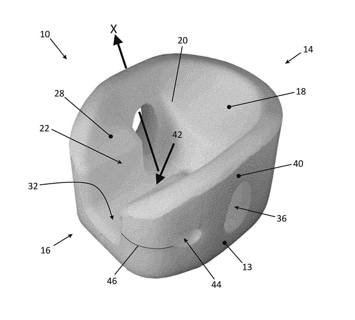
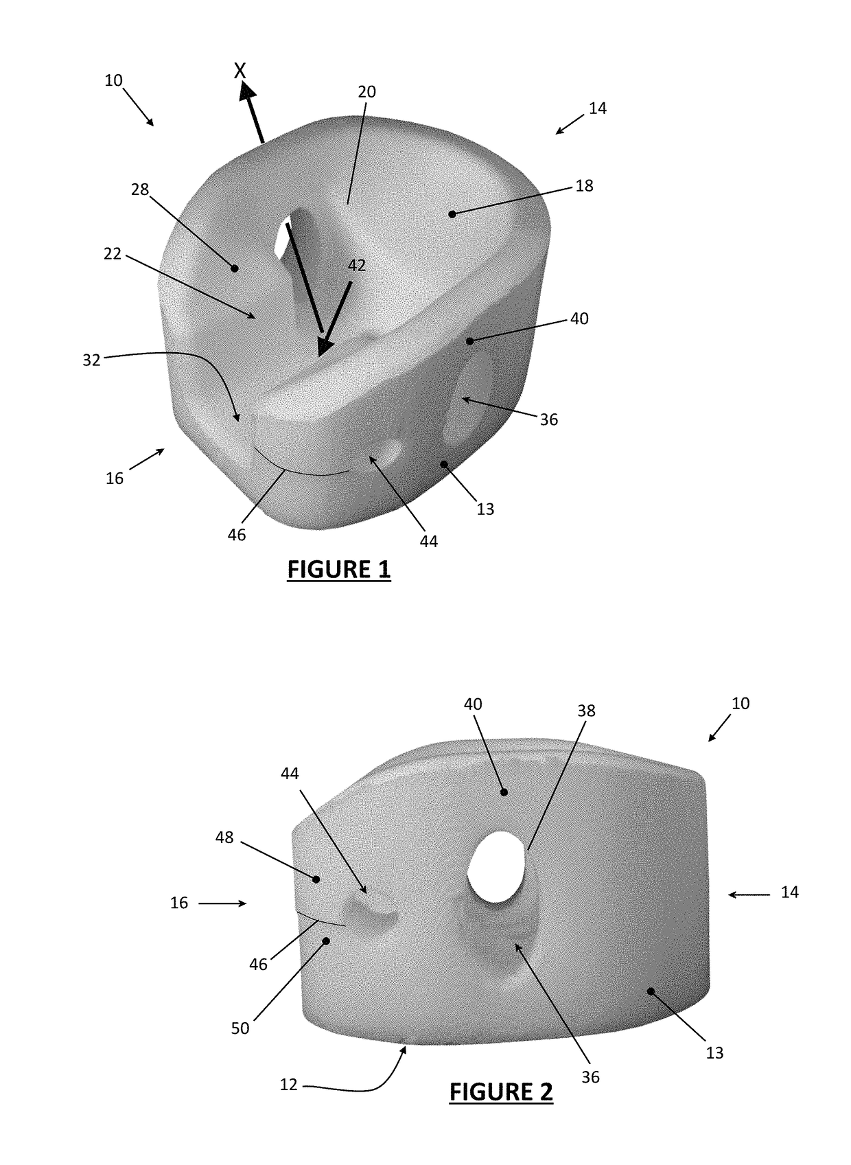
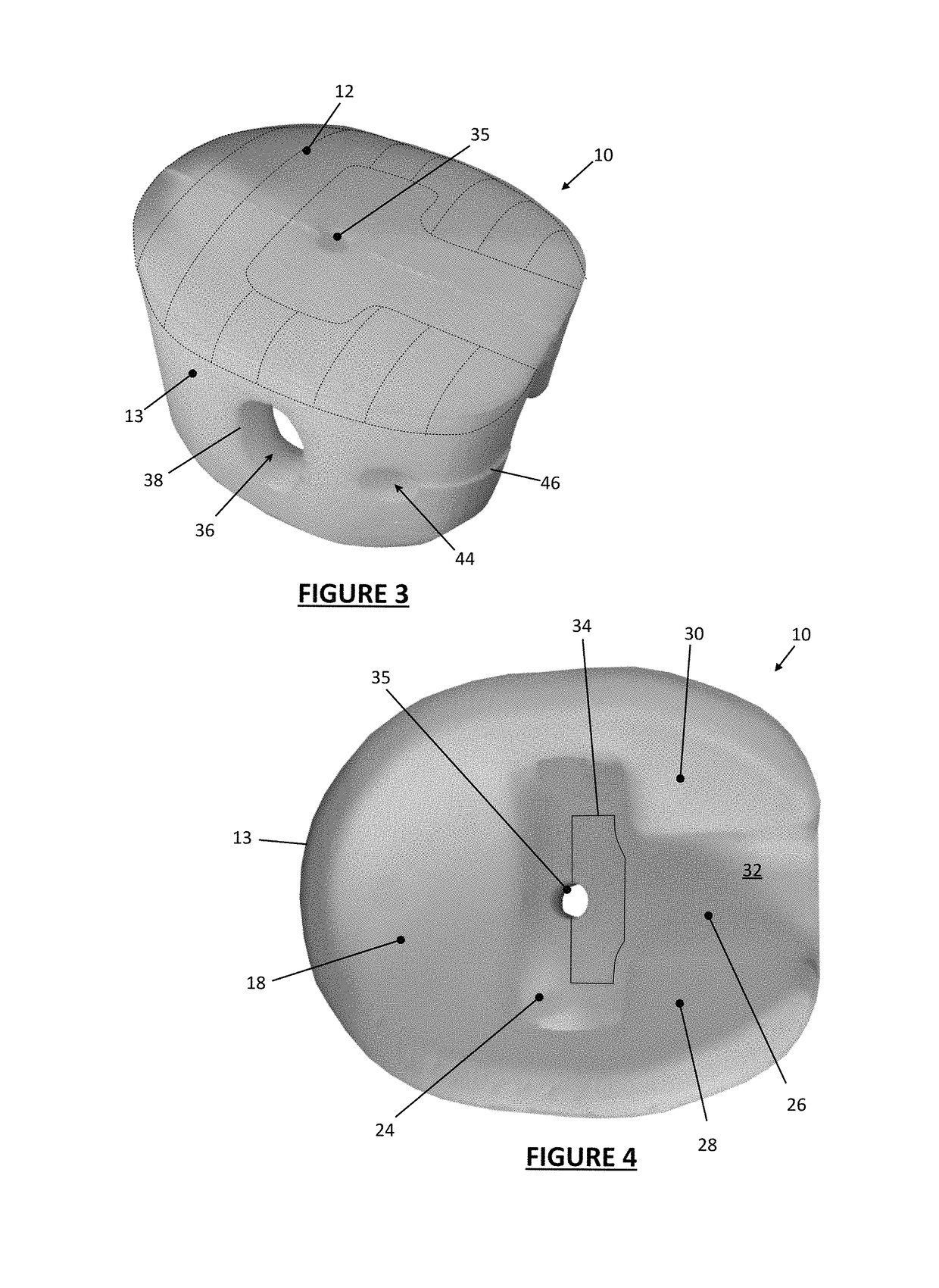
[0041]The first head support 10 represented in FIGS. 1 to 4 is intended for use in surgical procedures, with the patient in the prone position. It comprises a unitary body of foam material. Suitable foams for the purpose are known to the skilled person. Polyurethane foam is one suitable material. The material is compliant, which is to say that it is capable of yielding somewhat under the pressure applied to it in use by the face of the patient. It is also sufficiently resilient to recover its original shape after removal of that pressure.

[0042]The head support 10 may be offered as a single use (disposable) item. By avoiding re-use, transmission of infection from one patient to another is avoided without need of elaborate measures for disinfection. It may be supplied to the user in a sealed bag, giving protection against its contamination prior to use.

[0043]The head support 10 in this particular embodiment does not require, and is not provided with, any external frame or cradle....

second example

[0055

[0056]FIG. 5 represents a second head support 10a for this purpose. This differs in size and proportion from the first head support 10 but possesses otherwise equivalent features of shape and function. The same reference numerals are used in FIG. 5 as in the earlier drawings and the description of the relevant features will not be repeated. A conspicuous distinction between the first and second head supports 10, 10a is that in the latter the longitudinal extent of the cheek support portions 28, 30 is smaller in proportion to the size of the forehead support portion 18, this being a reflection of the relative proportions of the head of a child and of an adult.

[0057]Referring now to the remaining drawings, namely FIGS. 6, 7 and 9; these are perspective views of various variations of the design of head supports embodying the invention.

third example

[0058

[0059]The head support shown in FIG. 6 is of a shape and size, which has been designed for supporting the head / face of a child / infant and has similar features to those described previously. For the avoidance of repetition, identical reference signs have been used to identify identical features in FIG. 6 as they have in relation to the previous drawings.

[0060]The main difference between the embodiment shown in FIG. 6 and that shown, say, in FIG. 5, which is also for an infant, is that the shape of the head support 10, when viewed from above, is more U-shaped than rounded. In this embodiment, the viewing opening 36 is generally D-shaped, whereas in previously-described embodiments, it is generally oval. Nevertheless, the head support 10 has a curved portion 18, which, in use, supports the forehead of a prone-positioned patient, as well as curved portions 28, 30 for supporting the cheeks of a prone-positioned patient. The central void 22 provides an opening such that the ocular / na...


PUM


Abstract

The present invention relates to a head support for supporting a patient's head while the patient is in a prone position. The head support comprises a body of compliant material whose shape provides a forehead support region, at least one further support region for supporting a lower portion of the patient's face, and a void which accommodates the patient's eyes, nose and mouth in use. According to one aspect of the invention, a viewing opening is provided which faces laterally and provides in use a line of sight from the exterior of the head support into the void, the viewing opening having a periphery which is an unbroken loop.

Description

RELATED APPLICATION DATA[0001]This application claims the benefit of priority from GB Application No. GB1609405.4, filed May 27, 2016, the entire disclosure of which is hereby incorporated by reference herein in its entirety.TECHNICAL FIELD[0002]The present invention relates to apparatus for supporting a patient's head while the patient is in a prone position. It is especially, but not necessarily exclusively, suitable for use in medical procedures including surgery.BACKGROUND ART[0003]Various medical and therapeutic procedures require the patient to lie in a prone position—that is, to lie on his / her front, facing downwards. In particular, a range of surgical procedures including for example certain forms of spinal surgery require this mode of patient presentation. If the patient were simply supported on a flat bed, the head would naturally be turned to one side or the other but this is not desirable. Among other unwelcome effects, it puts the cervical spine in an abnormal position ...

Claims


Application Information

Patent Timeline
Patent Type & Authority Patents(United States)
IPC IPC(8): A47C20/02A61G13/12A47G9/10A61G7/07
CPCA47C20/026A47G9/1054A61G13/12A61G2200/325A61G7/072A61G13/121A61G13/1295A61G13/0054A61G7/1084A61G13/1215
Inventor BENNETTS, PAUL SHANE
Owner EC MEDICA
Why Eureka
Try Eureka