Methods and systems for surge control

a turbocharger and surge control technology, applied in the direction of gas pressure propulsion mounting, transportation and packaging, propulsion parts, etc., can solve the problems of nvh problems, compressors are prone to surge, so as to reduce forward flow through the compressor, improve peak power output, and increase fuel economy

Active Publication Date: 2018-05-29
FORD GLOBAL TECH LLC
View PDF4 Cites 0 Cited by
  • Summary
  • Abstract
  • Description
  • Claims
  • Application Information

AI Technical Summary

Benefits of technology

[0003]Compressor surge may be controlled by opening a compressor bypass valve (also known as a compressor recirculation valve) coupled in a bypass across the compressor to increase recirculation of boosted air from downstream of the compressor to upstream of the compressor. The resulting increase in compressor flow and reduction in compressor pressure ratio improves the compressor's margin to surge. One example of using a compressor bypass valve (CBV) for surge control is shown by Banker et al. in U.S. Pat. No. 9,174,637. Therein responsive to an indication of surge, a CBV is opened to dump boost pressure and increase compressor recirculation flow. In addition, throttle flow is reduced to a higher than desired level of airflow to move compressor operation away from the surge limit. The excess torque generated due to the higher than desired airflow is then addressed by increasing a load applied on the engine by an electric machine, such as by an electric motor.
[0004]However, the inventors have identified potential issues associated with reliance on a CBV. As one example, the CBVs add significant component cost. In engines configured with twin turbochargers, such as one turbocharger coupled to each engine bank, the costs are doubled. In addition to costs, there may also be durability concerns associated with excessive cycling of the CBVs. As such, this can result in warranty issues. Further, the addition of the CBV can add complexity to engine boost and torque control. In particular, the effects of the faster acting CBV can confound the control loop of a slower acting exhaust waste gate. Further still, the dumping of boost pressure by the CBV reduces boost efficiency.
[0007]As one example, a hybrid vehicle may be configured with an electric motor coupled to an energy storage system (e.g., a battery) and a boosted engine including a turbocharger. During engine operation, an intake compressor of the turbocharger may be used for providing a boosted intake air charge. While operating with boost, a controller may monitor compressor conditions, such as a compressor flow rate, a compressor pressure ratio, etc., to determine if compressor surge is likely. As the compressor operation approaches a surge limit, the controller may increase usage of motor torque (relative to engine torque) to meet a driver demand. The relative usage of motor torque may be varied with the likelihood of (or margin to) surge, as well as current state of charge of the battery. As a result of the increased use of motor torque, the battery state of charge may start to deplete. When compressor surge does subsequently occur, for example responsive to a sudden drop in torque demand during an operator pedal tip-out, the controller may adjust one or more engine torque actuators to substantially immediately limit the engine torque output to a level based on the compressor surge limit. In particular, engine torque may be limited so that compressor operation moves away from the surge limit. For example, engine torque may be limited so that airflow through the compressor is above a surge inducing pressure ratio. Motor torque is then adjusted based on the engine torque to meet the driver demand. For example, the engine torque may be limited to a level where the engine torque exceeds the driver demand, while the excess torque is absorbed at the battery. Since the battery was previously depleted in anticipation of surge, the battery's ability to accept charge is enhanced, and use of an electric motor to absorb the excess torque for surge control is improved.
[0008]In this way, by increasing motor torque usage in anticipation of compressor surge, a battery's charge accepting ability at a time of compressor surge is increased. The technical effect of limiting an engine torque responsive to surge is that a compressor pressure ratio may be improved, surge may be mitigated, and surge related issues (such as NVH) are alleviated, while avoiding the cost and other issues associated with a compressor bypass valve. By using the previously depleted battery to absorb any excess torque remaining after limiting the engine torque, driver demand can be met without impacting vehicle drivability. In particular, a “run-on” feel created by the excess torque can be overcome. In addition, the reliance on spark retard for addressing the excess torque is reduced, improving fuel economy. Overall, surge can be reduced without degrading the operator's drive feel and while meeting the operator torque demand.

Problems solved by technology

However, compressors are prone to surge.
For example, when an operator tips-out of an accelerator pedal, an engine intake throttle closes, leading to reduced forward flow through the compressor, and potentially compressor surge.
Surge can lead to NVH issues such as undesirable noise from the engine intake system.
However, the inventors have identified potential issues associated with reliance on a CBV.
As one example, the CBVs add significant component cost.
In addition to costs, there may also be durability concerns associated with excessive cycling of the CBVs.
As such, this can result in warranty issues.
Further, the addition of the CBV can add complexity to engine boost and torque control.
In particular, the effects of the faster acting CBV can confound the control loop of a slower acting exhaust waste gate.
Further still, the dumping of boost pressure by the CBV reduces boost efficiency.
As one example, there may be conditions when the electric motor is not able to absorb the excess torque, such as when a battery coupled to the motor has a higher than threshold charge and is not able to accept further charge.
If any excess torque remains, vehicle drivability may be affected.
As a result, vehicle fuel economy is degraded.
If the throttle is adjusted to reduce airflow through the compressor at a slower rate, surge may not be appropriately addressed and a time to torque may be affected.
As a result of the increased use of motor torque, the battery state of charge may start to deplete.
In particular, engine torque may be limited so that compressor operation moves away from the surge limit.
For example, engine torque may be limited so that airflow through the compressor is above a surge inducing pressure ratio.
For example, the engine torque may be limited to a level where the engine torque exceeds the driver demand, while the excess torque is absorbed at the battery.

Method used


Image

  • Methods and systems for surge control
  • Methods and systems for surge control
  • Methods and systems for surge control

Examples


Embodiment Construction

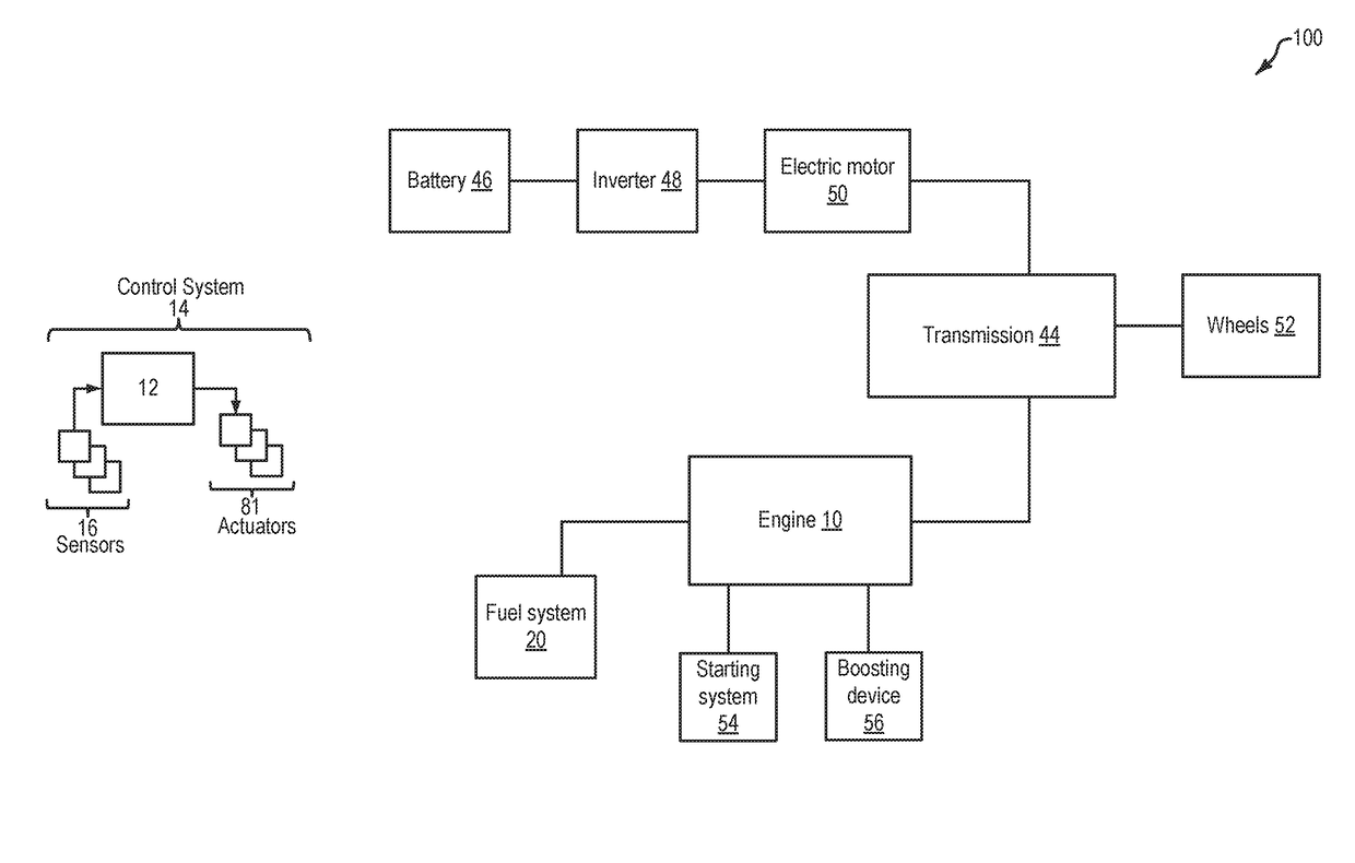
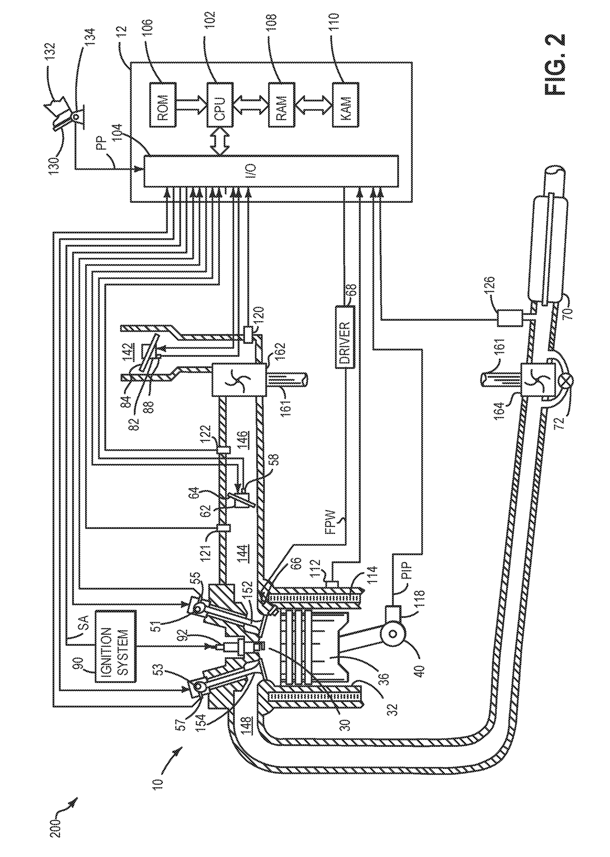
[0016]The following description relates to systems and methods for addressing compressor surge in a boosted engine system, such as the system of FIG. 2, configured in a hybrid electric vehicle, such as the vehicle of FIG. 1. A controller may be configured to perform a control routine, such as the routine of FIG. 3, to increase usage of motor torque in anticipation of compressor surge so as to deplete an energy storage system to a lower state of charge. During the incidence of surge, the controller may then adjust engine actuators to limit engine torque to a level where compressor flow is moved away from a surge limit (FIGS. 4-5). An example adjustment is shown with reference to FIG. 6. In this way, motor torque usage for mitigating surge can be improved.

[0017]FIG. 1 depicts a hybrid propulsion system 100 for a vehicle. In the depicted embodiment, the vehicle is a hybrid electric vehicle (HEV). Hybrid propulsion system 100 includes an internal combustion engine 10. Engine 10 is coupl...


PUM


Abstract

Methods and systems are provided for improving surge control. When surge conditions are anticipated, motor torque usage is increased to discharge a battery to a lower state of charge. When surge conditions actually occur, engine torque output is limited to a higher level than the engine output required to meet the reduced torque demand, while the excess wheel torque is offset by charging the battery to a higher state of charge.

Description

FIELD[0001]The present application relates to methods and systems for turbocharger surge control.BACKGROUND AND SUMMARY[0002]Engine systems may be configured with boosting devices, such as turbochargers or superchargers, for providing a boosted air charge and improving peak power outputs. The use of a compressor allows a smaller displacement engine to provide as much power as a larger displacement engine, but with additional fuel economy benefits. However, compressors are prone to surge. For example, when an operator tips-out of an accelerator pedal, an engine intake throttle closes, leading to reduced forward flow through the compressor, and potentially compressor surge. Surge can lead to NVH issues such as undesirable noise from the engine intake system.[0003]Compressor surge may be controlled by opening a compressor bypass valve (also known as a compressor recirculation valve) coupled in a bypass across the compressor to increase recirculation of boosted air from downstream of th...

Claims


Application Information

Patent Timeline
Patent Type & Authority Patents(United States)
IPC IPC(8): B60W20/17B60W10/08B60W10/06B60W20/13B60K6/40B60K6/24B60W10/26
CPCB60W20/17B60K6/40B60W10/06B60W10/08B60W10/26B60W20/13B60K6/24Y10S903/951B60W2510/0633B60W2540/10B60W2710/0666B60W2710/083B60W2710/244B60Y2200/92B60Y2300/205Y10S903/905Y10S903/93B60W20/10B60W2510/06B60W50/0097B60W2510/244Y02T10/62
Inventor MILLER, KENNETH JAMESSHELBY, MICHAEL HOWARDLEONE, THOMAS G.
Owner FORD GLOBAL TECH LLC
Why Eureka
Try Eureka