Ventilation system for an internal combustion engine

Inactive Publication Date: 2018-06-05
REINZ DICHTUNGS +1
View PDF29 Cites 1 Cited by
  • Summary
  • Abstract
  • Description
  • Claims
  • Application Information

AI Technical Summary

Benefits of technology

[0012]It is therefore the object of the present invention to provide for a ventilation system for the ventilation and the aeration of an internal combustion engine, which comprises an optimized demand in installation space, optimized cost, a reduced amount of components, a simpli

Problems solved by technology

This is of particular importance since nitrogen oxides are present in the blow-by gases, which cause an aging of the engine oil.
This results in high tooling expense for the production

Method used


Image

  • Ventilation system for an internal combustion engine
  • Ventilation system for an internal combustion engine
  • Ventilation system for an internal combustion engine

Examples


Example

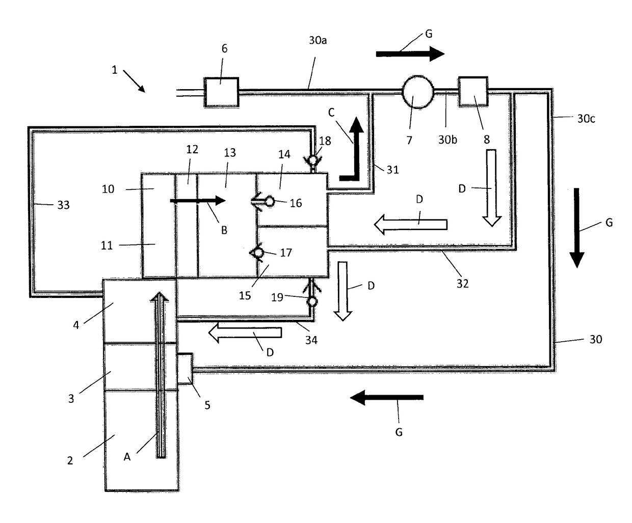
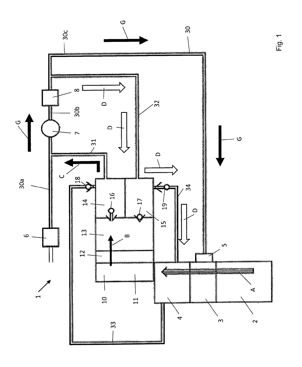
[0049]FIG. 1 shows an internal combustion engine with a crank case 2, a cylinder head 3, a cylinder head cover 4 and an inlet for the aeration 5. Reference number 1 denotes a ventilation system according to the present invention.

[0050]Further, the intake section of the internal combustion engine with air filter 6, supercharger 7, throttle flap 8 and intake pipe 30 with the pipe sections 30a, 30b and 30c is shown in FIG. 1. The fresh air here is guided via the filter 6 and the pipe section 30a of the intake section to the supercharger 7. As the supercharger, one can for instance use a compressor or an exhaust turbo charger. The fresh air is guided from the supercharger to the throttle flap 8 via the pipe section 30b of the pipe 30 and from there further to the inlet for the aeration 5 via the pipe section 30c.

[0051]The ventilation system comprises an air-oil separator 10. This air-oil separator 10 comprises an inlet space 11, a separation element 12 for the separation of oil mist an...


PUM

PropertyMeasurementUnit
Pressureaaaaaaaaaa
Pressureaaaaaaaaaa
Pressureaaaaaaaaaa

Abstract

A ventilation system for the ventilation and for the aeration of an internal combustion engine is described and depicted. The ventilation system may have an intake pipe and a supercharger in the intake pipe, and an air-oil separator for the separation of oil and/or oil mist from blow-by gases with at least one inlet and at least one outlet.

Description

BACKGROUND OF THE INVENTION[0001]The present invention relates to a ventilation system for the ventilation and for the aeration of an internal combustion engine. Such ventilation systems are in particular used for the ventilation and the aeration of the crank case of an internal combustion engine. The present invention further relates to a cylinder head cover and an internal combustion engine, which comprise a ventilation system according to the invention.[0002]The ventilation systems mentioned above are in particular, but not only, used for the ventilation of a crank case in internal combustion engines. In the following, the invention is therefore described using the ventilation and aeration of a crank case as an example. For environmental reasons, the blow-by gases occurring there are usually fed back, e.g. to the intake section of the internal combustion engine. To this end, the crank case is ventilated. On the other hand and also for environmental reasons, the pressure in the cr...

Claims


Application Information

Patent Timeline
IPC IPC(8): F01M13/04F01M13/02B01D45/16F01M13/00
CPCF01M13/04B01D45/16F01M13/02F01M13/0416F01M2013/0438F01M2013/0038F01M2013/0044F01M2013/027F01M13/022
Inventor ERDMANN, CHRISTOPHZITAROSA, FRANCESCO
Owner REINZ DICHTUNGS
Why Eureka
Try Eureka