Drive control system for vehicle

a technology for controlling system and vehicle, applied in the direction of motor/generator/converter stopper, multiple dynamo-motor starters, dynamo-electric converter control, etc., can solve the problems of short stop time, deviation from a target voltage, and change in consumption energy, so as to reduce the loss of direct current/direct current converter, reduce the driving force of the first motor, and prolong the stop time

Active Publication Date: 2018-06-12
TOYOTA JIDOSHA KK
View PDF4 Cites 0 Cited by
  • Summary
  • Abstract
  • Description
  • Claims
  • Application Information

AI Technical Summary

Benefits of technology

[0009]The invention provides a drive control system for a vehicle, which achieves both a reduction in the loss of a direct current / direct current converter and suppression of a decrease in driving performance.
[0015]With the above-described drive control system for a vehicle according to the invention, it is possible to achieve both a reduction in the loss of the direct current / direct current converter and suppression of a decrease in driving performance. Specifically, with the drive control system according to the invention, when the required driving force changes during the stop of the direct current / direct current converter, the second motor outputs the change in the required driving force. Thus, it is possible to suppress a rapid change in the driving force of the first motor. Therefore, it is possible to extend the stop time of the direct current / direct current converter by suppressing a rapid increase in the difference between a voltage transformed by the direct current / direct current converter and a target voltage, so the loss of the direct current / direct current converter is reduced. It is possible to achieve the required driving force of the vehicle, so it is possible to suppress a decrease in driving performance.
[0018]With the above-described drive control system for a vehicle, during a stop of the direct current / direct current converter, the driving force of the first motor is reduced and the driving force of the second motor is increased while the driving force of the vehicle is kept constant. Thus, it is possible to reduce the driving force of the first motor, so it is possible to extend the stop time of the direct current / direct current converter. Therefore, the loss of the direct current / direct current converter is reduced. A decrease in the driving force of the first motor is compensated by an increase in the driving force of the second motor, so it is possible to suppress a decrease in driving performance.

Problems solved by technology

However, when a change in the driving force of the first motor increases as a result of a change in the required driving force of the vehicle increases during the stop time, a change in consumption energy increases, with the result that a transformed voltage may decrease in a short period of time and a deviation from a target voltage may increase.
In existing control, when the vehicle driving force is kept constant in a high state even when the vehicle driving force is kept constant during a stop time of the direct current / direct current converter, an electric power consumption on the first motor side with respect to the direct current / direct current converter increases, so there is a concern that the stop of the direct current / direct current converter is early cancelled.
On the other hand, when a switching operation stop time is extended by merely limiting the driving torque of the first motor during the stop time of the direct current / direct current converter, there is a concern that the driving performance of the vehicle decreases.

Method used


Image

  • Drive control system for vehicle
  • Drive control system for vehicle
  • Drive control system for vehicle

Examples


Embodiment Construction

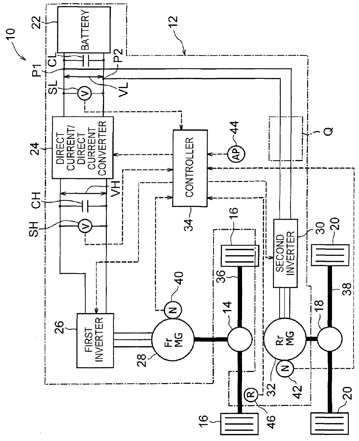
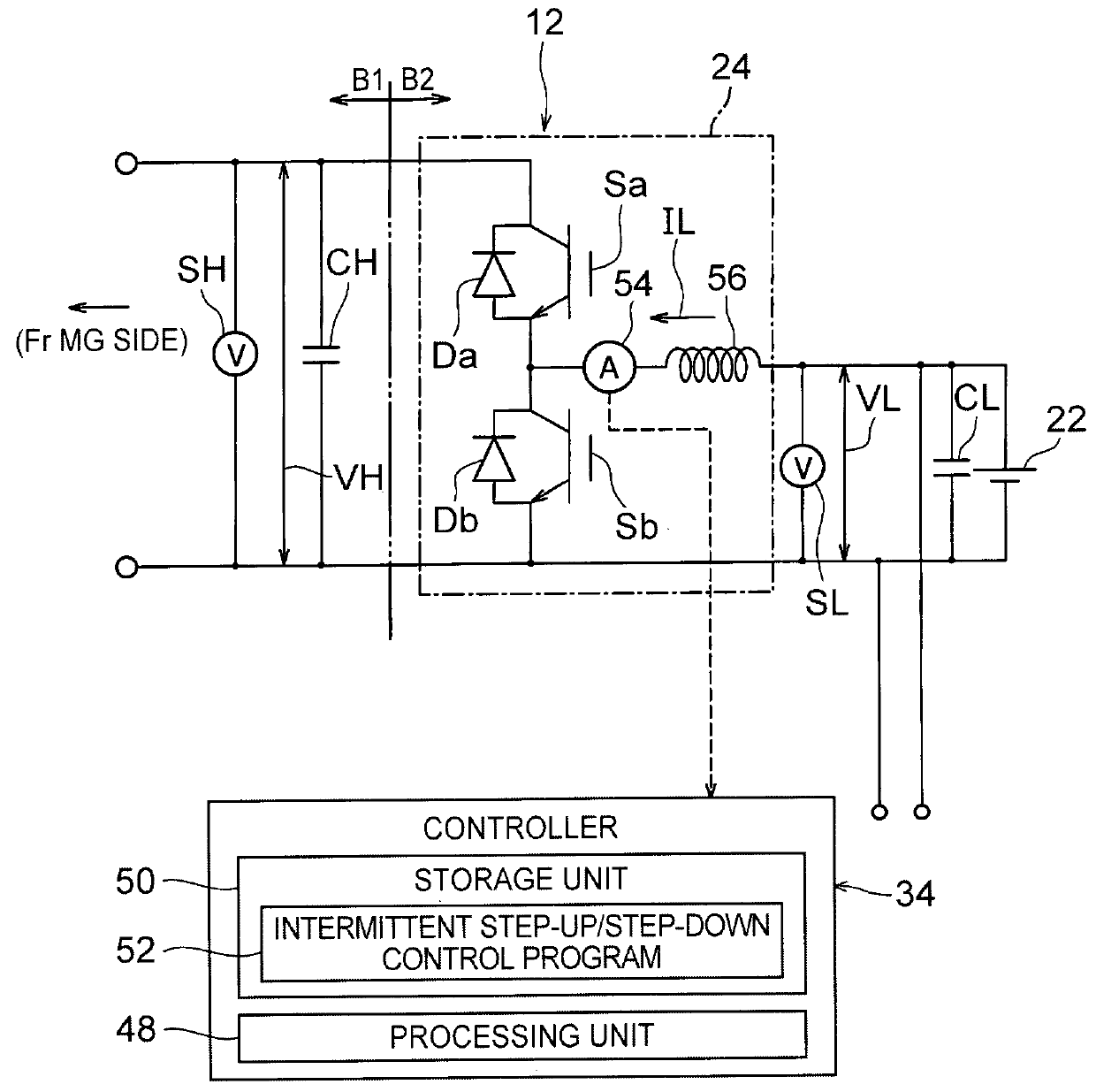
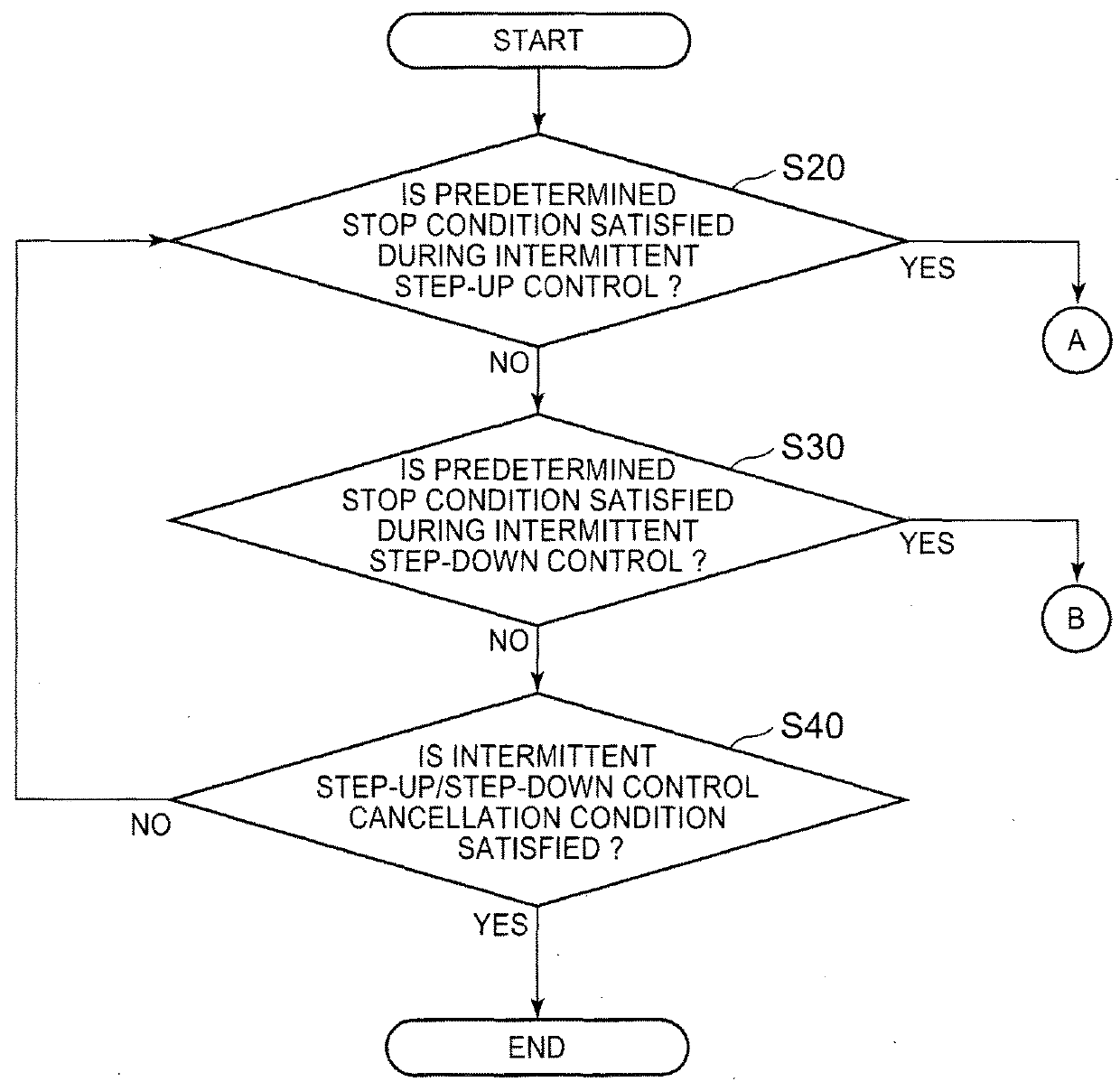
[0032]Hereinafter, embodiments of the invention will be described in detail with reference to the accompanying drawings. Motor generators each having the function of an electric motor and the function of a generator will be described as a first motor and a second motor. Instead, the first motor and the second motor do not need to have the function of a generator. A direct current / direct current converter having a step-up / step-down function will be described. Instead, a direct current / direct current converter may be configured to merely have only the step-up function. A controller having the function of executing intermittent step-up / step-down control, that is, executing intermittent step-up control or intermittent step-down control while switching between the intermittent step-up control and the intermittent step-down control in response to fulfillment of a predetermined condition, will be described. Instead, the controller may be configured to have the function of executing only in...


PUM


Abstract

A drive control system includes a battery, a direct current / direct current converter, a first motor, a second motor, and a controller. The battery is a direct-current power supply. The direct current / direct current converter is connected to the battery. The first motor is connected to the direct current / direct current converter, and drives one of a front wheel and a rear wheel. The second motor is connected to the battery, and drives the other one of the front wheel and the rear wheel, which is different from the wheel that the first motor drives. The controller controls step-up operation of the direct current / direct current converter, and executes intermittent step-up control. When a required driving force of a vehicle changes during a stop of the direct current / direct current converter through the intermittent step-up control, the second motor outputs an amount of change in the required driving force.

Description

BACKGROUND OF THE INVENTION[0001]1. Field of the Invention[0002]The invention relates to a drive control system for a vehicle and, more particularly, to motor torque control in intermittent step-up control over a direct current / direct current converter.[0003]2. Description of Related Art[0004]There is known an electromotive vehicle, such as a hybrid vehicle, an electric vehicle and a fuel-cell vehicle. The hybrid vehicle is equipped with an electric motor and an engine, and travels by using at least one of the electric motor and the engine as a driving source. The electric vehicle is equipped with an electric motor as a driving source. The electromotive vehicle may transform the voltage of a direct-current power supply, such as a battery, with the use of a direct current / direct current converter, supply electric power having the transformed voltage to an inverter, convert the electric power to alternating-current power with the use of the inverter, and supply the electric power to a...

Claims


Application Information

Patent Timeline
Patent Type & Authority Patents(United States)
IPC IPC(8): H02P1/54H02M1/088B60K1/02H02P3/18B60L7/14H02P27/06H02M3/158H02P5/46H02M1/00
CPCH02P5/46B60K1/02B60L7/14H02M3/158H02P3/18H02P27/06H02M1/088H02M2001/0054B60L15/2045H02M3/1582Y02T10/64Y02T10/72H02M1/0054H02M1/0032
Inventor ONO, TOSHIKAZU
Owner TOYOTA JIDOSHA KK
Why Eureka
Try Eureka