Wettability and fluid displacement in a well

Inactive Publication Date: 2001-01-02
HALLIBURTON ENERGY SERVICES INC
View PDF16 Cites 50 Cited by
  • Summary
  • Abstract
  • Description
  • Claims
  • Application Information

AI Technical Summary

Benefits of technology

In specific implementations, this invention is particularly applicable to wettability evaluation of spacers or preflushes suitable to water-wet downhole surfaces to which cement is expected to bond during a well cementing operation performed after the well has been drilled using oil or synthetic-based drilling fluids, for example. The present inven

Problems solved by technology

Bonding of the cement to the tubular string or to the wellbore surface can be less than desirable if the string and wellbore surfaces are not conducive to cement bonding.
Formation of a micro-annu

Method used


Image

  • Wettability and fluid displacement in a well
  • Wettability and fluid displacement in a well
  • Wettability and fluid displacement in a well

Examples


Example

Weight of Composition Composition in Grams oleaginous fluid 148 Ca(OH).sub.2 (lime) 3.5 organophilile clay 4 emulsifier 8 wetting agent 4 25% CaCl.sub.2 brine 106 barite 247

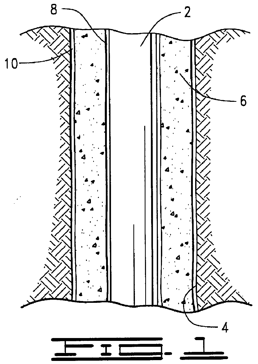
Referring to FIG. 1, a tubular string 2 (e.g., a drill string, production tubing string, casing or liner) is shown after it has been cemented into a suitably drilled wellbore 4. Cement 6 is placed in known manner (e.g., by pumping) in the annulus defined between the outer surface of the tubular string 2 and the surface of the cut wellbore 4.

Also represented in FIG. 1 is a thin layer 8 between the tubular string 2 and the inner surface of the column of cement 6. This does not necessarily extend along the entire length of the tubular string 2 or column of cement 6, but it is shown in FIG. 1 to illustrate what is referred to as a micro-annulus made of, typically, a coating of the drilling mud or other fluid previously in the well before displacement by the cement 6.

If the layer 8 is not suitably removed and the surf...


PUM


Abstract

An inverter fluid that intermixes with a non-aqueous (e.g., oil) external/aqueous internal fluid to cause external/internal inversion is designed. This includes testing a selected inverter fluid with a test fluid having a composition nominally equivalent to the composition of the non-aqueous external/aqueous internal fluid. A quantity of the designed inverter fluid is made and placed in the annulus of a well, such as an oil or gas well, to remove the non-aqueous external/aqueous internal fluid on at least a portion of one or more surfaces of the annulus. This can include pumping the inverter fluid along with a stream of cement. The inverter fluid displaces at least part of the non-aqueous external/aqueous internal fluid in the annular region and inverts the coating of non-aqueous external/aqueous internal fluid sufficient to remove the coating ahead of the cement. Determining a suitable inverter fluid comprises: measuring a parameter related to electrical conductivity of an initial mixture including (1) a test fluid having a composition nominally equivalent to the non-aqueous external/aqueous internal fluid and (2) part of a selected inverter fluid; and adding a further part of the selected inverter fluid to the initial mixture until the measured parameter indicates the external/internal phases of the test fluid have inverted.

Description

BACKGROUND OF THE INVENTIONThis invention relates generally to displacing fluids and water-wetting surfaces within a well, such as an oil or gas well. In one specific example, the present invention facilitates proper bonding of cement to side surfaces of an annulus in the well in which the cement is placed. This includes determining suitable displacement fluids that sufficiently wet the sides of the annulus to enable proper cement bonding. The present invention has applicability other than cementing, but in such other applications it still pertains to wettability and determining compositions for achieving suitable water-wetting within an oil or gas well.In one manner of drilling a well, "drilling mud" is pumped into a rotated drill string to which a drill bit is attached. The mud typically exits through openings in the drill bit to lubricate the bit and to carry cuttings up an annulus between the drill string and the wellbore for disposal at the surface. One type of drilling mud is ...

Claims


Application Information

Patent Timeline
IPC IPC(8): E21B33/13
CPCE21B33/13
Inventor HEATHMAN, JAMES F.WILSON, J. MICHAELCANTRELL, JAMES H.
Owner HALLIBURTON ENERGY SERVICES INC
Why Eureka
Try Eureka