Electronic candle simulator

a simulator and candle technology, applied in the field of electronic candle simulators, can solve the problems of impracticality or too expensive, impracticality of candle use, etc., and achieve the effect of obtaining energy and moving easily

Inactive Publication Date: 2001-05-08
ST LOUIS RAYMOND F
View PDF13 Cites 29 Cited by
  • Summary
  • Abstract
  • Description
  • Claims
  • Application Information

AI Technical Summary

Benefits of technology

The change in brightness from a first level to a second and back to the first so as to produce a flicker during successive periods should occur at a rate between two and ten Hz with rates between four and one-half Hz and six Hz inclusive being preferred. When the first level is lower than the second, the flicker is an increase in brightness during the spaced periods, herein referred to as a positive flicker. This is preferred to the first level being higher than the second so as to produce a reduction in brightness during the spaced periods, herein referred to as a negative flicker. Furthermore, it is preferable that there be a ten to twenty percent change in brightness between the levels so that the light is not turned on and off because this tends to produce blinking rather than flickering. A blinking effect is also avoided by making the changes in brightness occur in a random manner or in a sequence that appears to be random.
An electronically simulated candle of this invention can be energized by a battery so as to be easily moved about or it can obtain its energy by being plugged into an A.C. power outlet.

Problems solved by technology

There are a number of situations where a candle is impracticable or too expensive.
It would, for example, be impractical to use a candle for votive purposes in a cemetery, and in some places fire safety regulations would prevent it.
Although candles are often used at dining tables in a restaurant, they are very expensive.

Method used


Image

  • Electronic candle simulator
  • Electronic candle simulator
  • Electronic candle simulator

Examples


Embodiment Construction

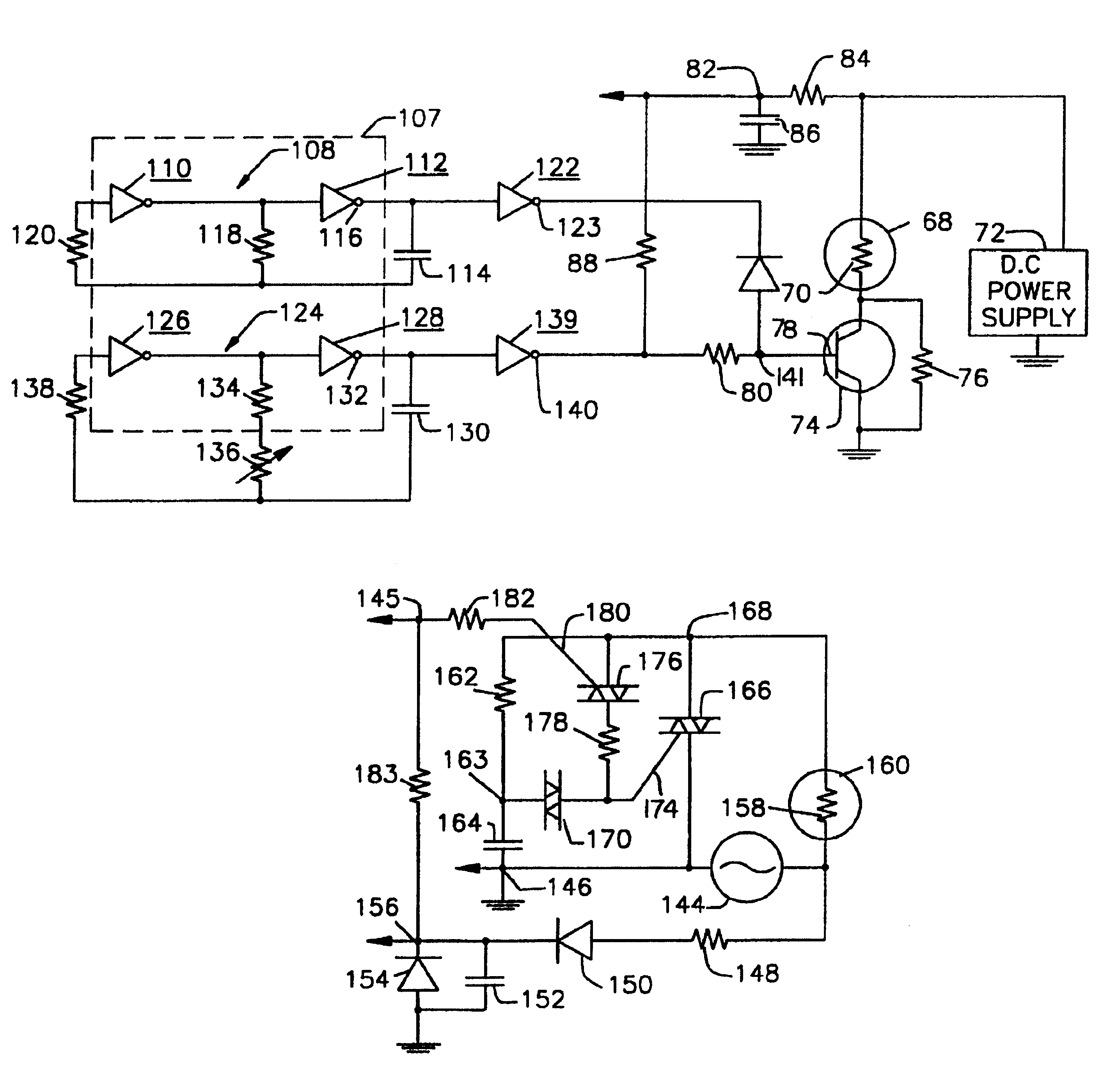
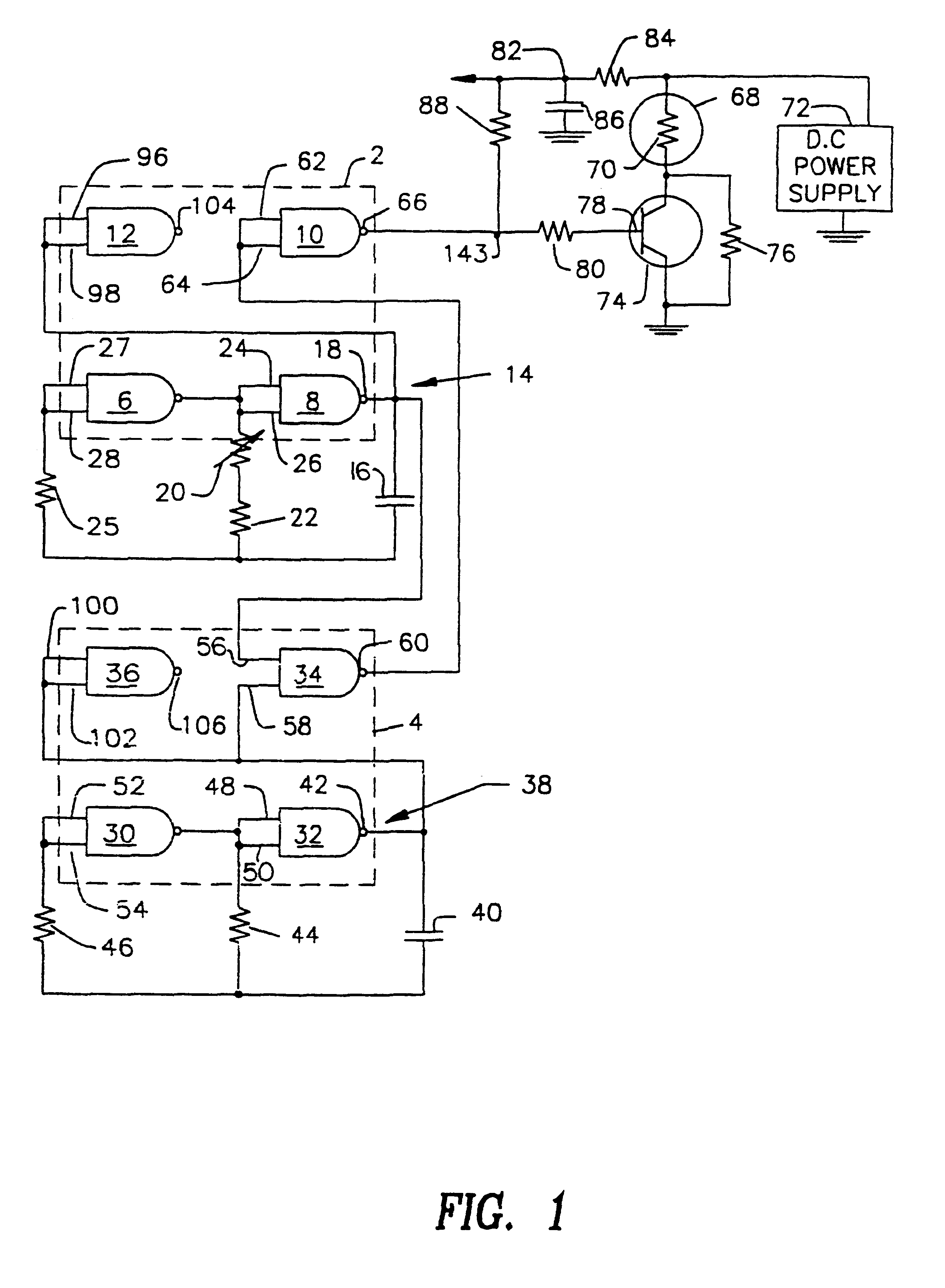
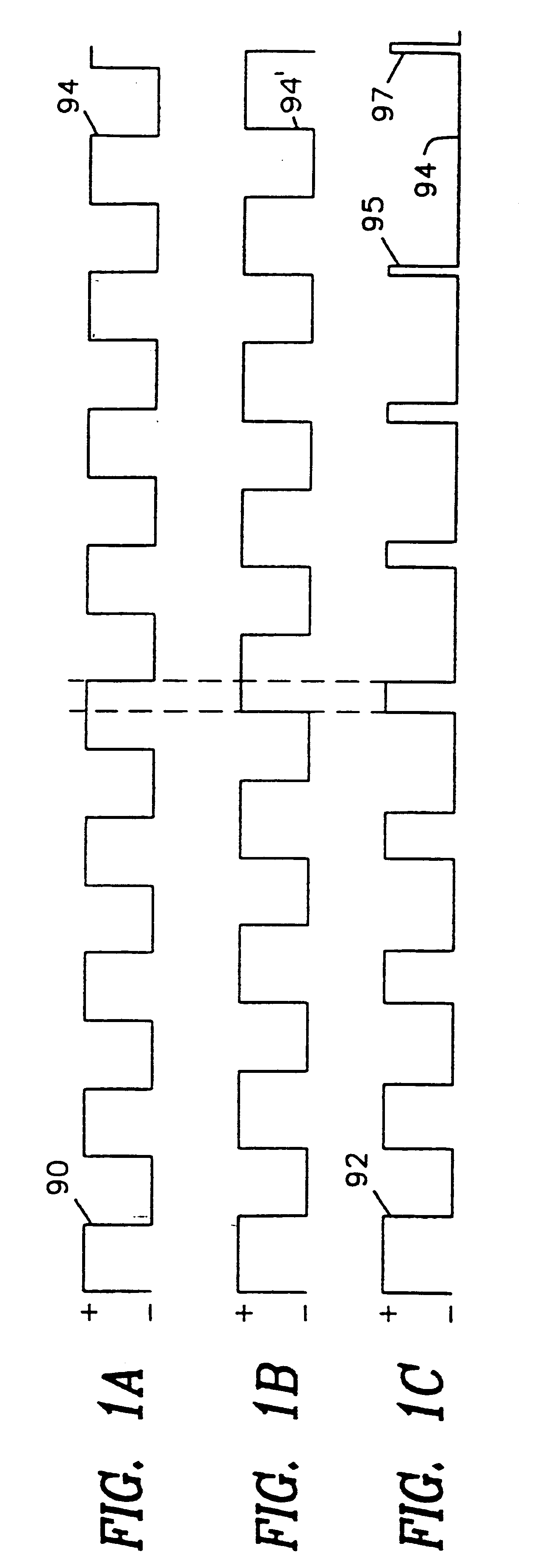
Reference is made to the schematic diagram of FIG. 1, which shows a circuit comprised of two chips 2 and 4 in rectangles formed by dashed lines that, for example, may be 4011's. The chip 2 is comprised of four NAND gates 6, 8, 10 and 12. The NAND gates 6 and 8 are coupled so as to form a first multivibrator oscillator 14 that outputs square waves such as those illustrated in FIG. 1A, for example. In the particular embodiment shown, the coupling is comprised of a capacitor 16 having one side connected to the output 18 of the NAND gate 8, a variable resistor 20 and a resistor 22 connected in series between the other side of the capacitor 16 and the inputs 24 and 26 of the NAND gate 8 and a resistor 25 connected between the other side of the capacitor 16 and inputs 27 and 28 of the NAND gate 6.

The chip 4 is comprised of four NAND gates 30, 32, 34 and 36 the NAND gates 30 and 32 are coupled so as to form a second multivibrator oscillator 38 that outputs the square waves such as those il...


PUM


Abstract

Apparatus for simulating a candle flame in which the current through the filament of a bulb is varied from a first value to a second value and back to the first value during spaced periods that vary from a period of maximum duration to a period of minimum duration that produces no observable flicker in an apparently random manner.

Description

BACKGROUND OF THE INVENTIONThere are a number of situations where a candle is impracticable or too expensive. It would, for example, be impractical to use a candle for votive purposes in a cemetery, and in some places fire safety regulations would prevent it. Although candles are often used at dining tables in a restaurant, they are very expensive.BRIEF SUMMARY OF THE INVENTIONTherefore, in accordance with this invention, an electrical candle is provided that simulates the flickering flame of an actual candle. An electrical circuit generates a control signal for varying the brightness of light emitted by a light emitting means between a first level and a second level and back to the first level during spaced periods of gradually increasing duration followed by periods of gradually decreasing duration, there being a number of periods of such short duration as to cause no noticeable change in brightness. In accordance with an aspect of this invention a suitable control signal may be d...

Claims


Application Information

Patent Timeline
Patent Type & Authority Patents(United States)
IPC IPC(8): H05B39/09H05B39/00
CPCF21S10/04H05B39/09Y10S362/81F21W2121/00F21Y2115/10
Inventor ST. LOUIS, RAYMOND F.
Owner ST LOUIS RAYMOND F
Why Eureka
Try Eureka