At frequency phase shifting circuit for use in a quadrature clock generator

Inactive Publication Date: 2001-11-20
RAMBUS INC
View PDF71 Cites 35 Cited by
  • Summary
  • Abstract
  • Description
  • Claims
  • Application Information

AI Technical Summary

Problems solved by technology

Cyclic variations from the desired phase difference between the output clock signals of the quadrature clock generator result in "jitter."
For DLL purposes, the jitter of the quadrature clock generator affects the timing margins of the DLL, increasing lock acquisition time for the DLL.
Wherein frequency dividing quadrature clock generators are capable of providing adequate jitter performance, a DL

Method used


Image

  • At frequency phase shifting circuit for use in a quadrature clock generator
  • At frequency phase shifting circuit for use in a quadrature clock generator
  • At frequency phase shifting circuit for use in a quadrature clock generator

Examples


Embodiment Construction

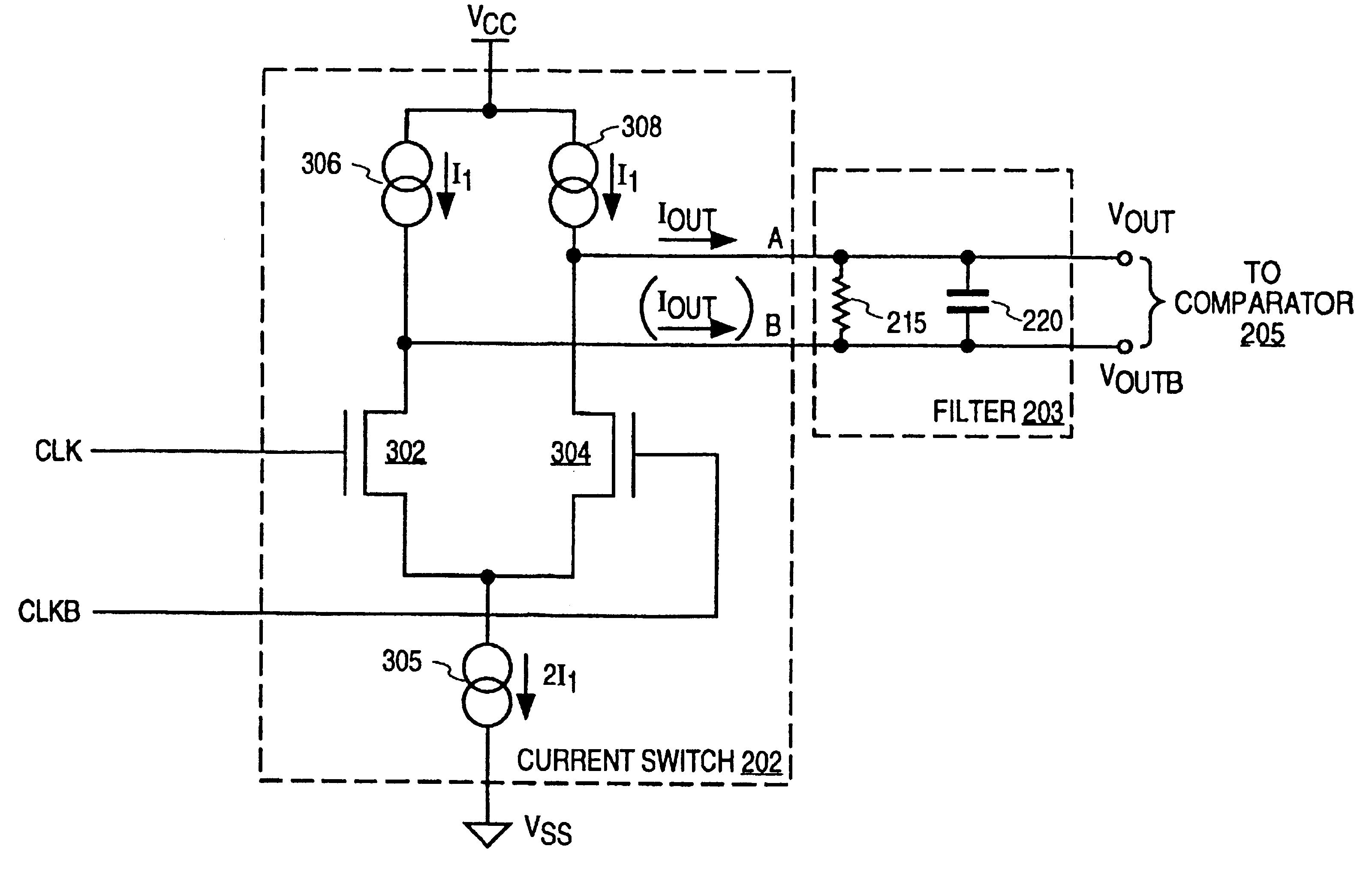
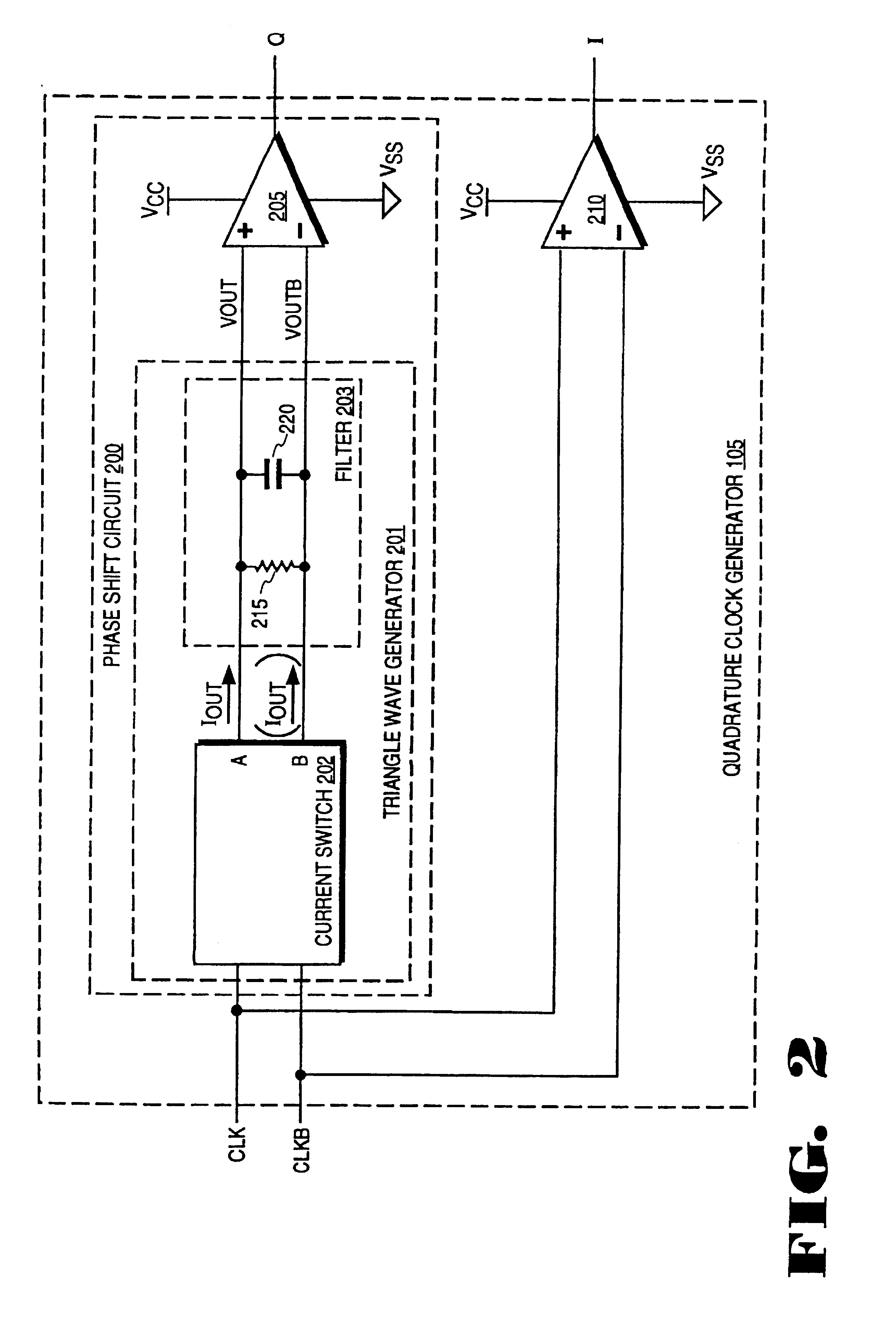
A phase shifting circuit that operates at frequency and may be incorporated as part of a quadrature clock generator is described herein. The phase shifting circuit generally comprises a triangle wave generator coupled in series with a comparator. The triangle wave generator receives a periodic input signal and outputs two complementary triangle wave signals. The comparator compares the value of the first triangle wave to the value of the second triangle wave, outputting a logic high value when the first triangle wave is greater than the second triangle wave and a logic low value when the first triangle wave is less than the second triangle wave.

The output of the comparator transitions between logic high and logic low values when the first and second triangle waves are equal. Assuming that the input signal has a 50% duty cycle, the output signal of the comparator transitions approximately 90 degrees out of phase with the transitions of the input signal. The phase shift circuit may be...


PUM


Abstract

A phase shifting circuit that may be used as part of a quadrature clock generator. The phase shifting circuit comprises a triangle wave generator coupled to receive an input reference signal. The triangle wave generator outputs a pair of complementary triangle wave signals in response to the input reference signal. A comparator having a pair of inputs is coupled to receive the pair of complementary triangle wave signals. The comparator outputs an output signal having a predetermined phase relationship with the input reference signal in response to a comparison between the pair of complementary triangle wave signals.

Description

FIELD OF THE INVENTIONThe present invention relates generally to phase shifting circuits and more particularly to a phase shifting circuit that may be used in quadrature clock generator for .[.for.]. providing quadrature output signals.BACKGROUND OF THE INVENTIONA quadrature clock generator may be used in a delay locked loop (DLL) to provide two clock signals that are 90 degrees out of phase with one another. Typically, a first output clock signal (the "I" output clock signal) is in phase with the input reference clock signal, and a second output clock signal (the quadrature or "Q" output clock signal) is 90 degrees out of phase with the input reference clock signal. Both output clock signals of the quadrature clock generator have the reference frequency. The output clock signals are phase mixed to provide a desired phase difference or delay between the output clock signal of the DLL and the input reference clock.Cyclic variations from the desired phase difference between the output...

Claims


Application Information

Patent Timeline
IPC IPC(8): H03K5/13H03H11/02H03L7/08H03K5/151H03K5/15H03H11/18H03L7/081H03K5/00
CPCH03H11/18H03K5/133H03K5/151H03K2005/00208H03L7/0814H03L7/0816H03L7/0812
Inventor DONNELLY, KEVIN S.CHAU, PAK SHING
Owner RAMBUS INC
Why Eureka
Try Eureka