CRT having color filter with a special green filter

Inactive Publication Date: 2002-06-18
KK TOSHIBA
View PDF13 Cites 3 Cited by
  • Summary
  • Abstract
  • Description
  • Claims
  • Application Information

AI Technical Summary

Benefits of technology

An object of the present invention is to provide a color picture tube for satisfactorily improving the luminance of the effective display screen, the contra

Problems solved by technology

However, with the conventional technologies, it is difficult to improve both the brightness and contrast.
However, when the energy of the electron beam is increased, the current consumption of the color picture tube increases.
Thus, the power consumption of the color display apparatus increases.
Practically, it is very difficult to equalize the wall thickness of the entire face plate of the flat type color picture tube.
However, in this case, the power consumption increases.
Thus, the total power consumption of the color picture tube remarkably increases.
However, with this method, a good result cannot be obtained.
Nevertheless, the filter performance of the color filter layer composed of such an inorganic pigment is not satisfactory.
In other words, with conventional pigments for green cells, satisfactory selective abso

Method used


Image

  • CRT having color filter with a special green filter
  • CRT having color filter with a special green filter
  • CRT having color filter with a special green filter

Examples


Embodiment Construction

With reference to the accompanying drawings, a color picture tube according to an embodiment of the present invention will be described in detail.

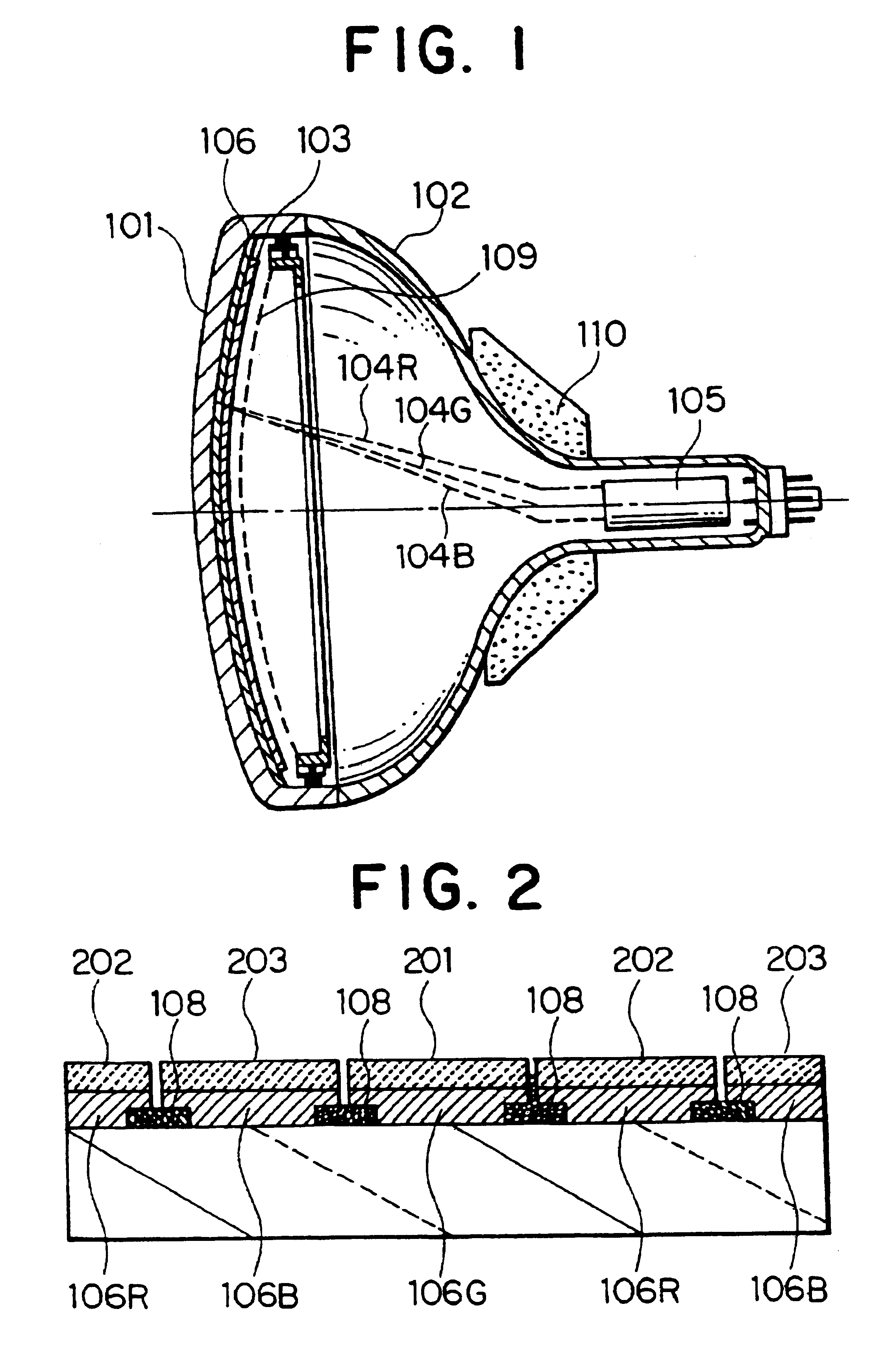
As shown in FIG. 1, a color picture tube 100 has a face plate 101 that has light transmissivity of 60% or more and that has an effective display surface for displaying a picture. The glass wall thickness of the face plate 101 radially increases with a predetermined change ratio. A funnel 102 that is a hollow cone with a tube extending from the smaller rear end is disposed on the rear end of the face plate 101. The front end of the funnel 102 is connected to the rear end of the face plate 101. Thus, a sealed vessel as a sheath of the color picture tube is formed.

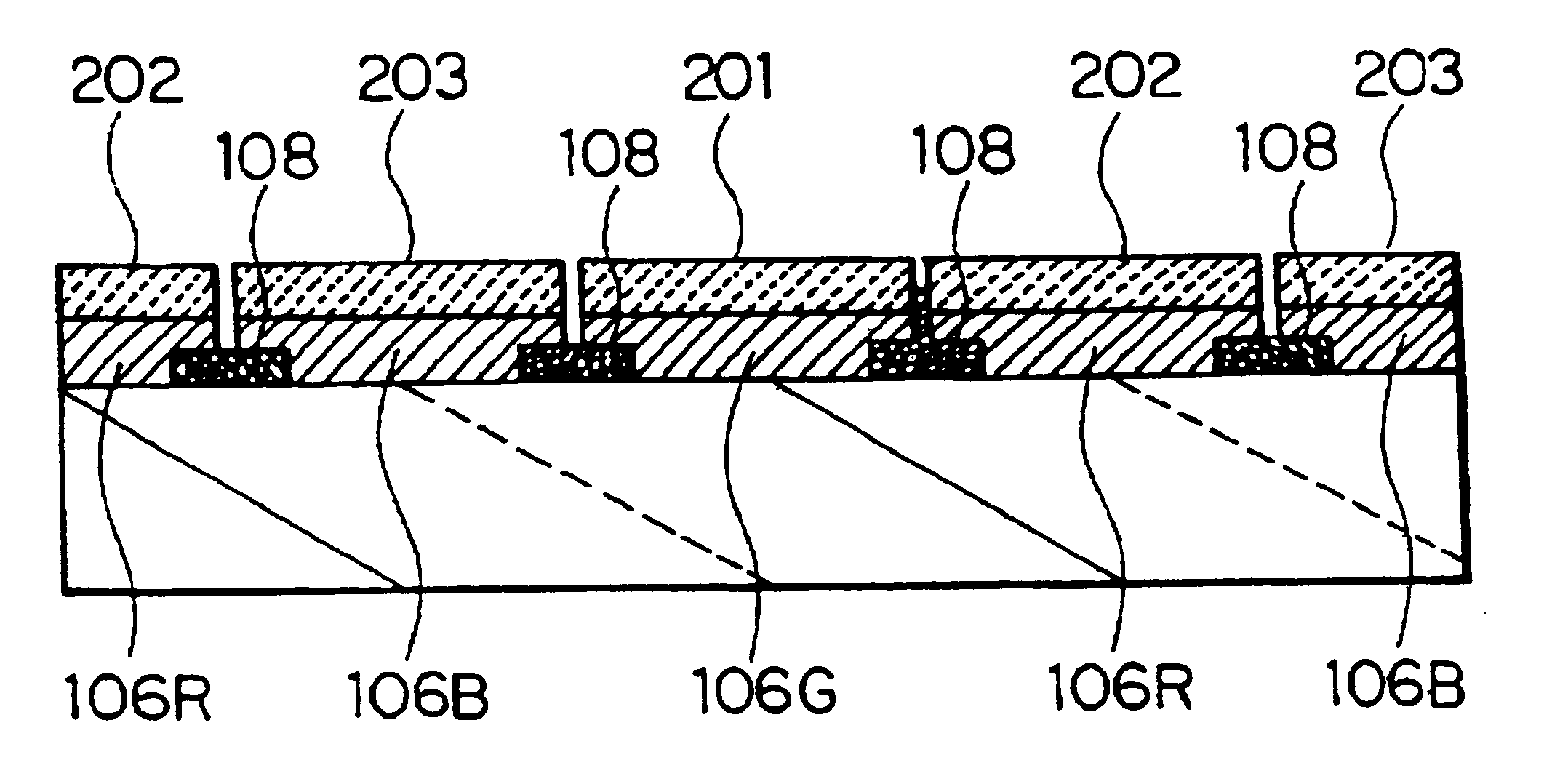
A fluorescent substance layer 103 is formed on the inner surface of the effective display surface of the face plate 101.

An electric gun 105 is disposed inside the rear end of the funnel 102. The electron gun 105 scans and radiates an electron beam to the fluorescent substance layer ...


PUM


Abstract

A color picture tube is disclosed, that comprises an outer sheath having a electron gun, the outer sheath being airtightly sealed, a face plate having light transmissivity and disposed on the front surface of the outer sheath, and a large number of red, blue, and green pixels regularly arranged inside the face plate, wherein the pixels have a fluorescent substance layer and a color filter, the fluorescent substance layer being lit by a radiation of an electron beam, the color filter being disposed between the fluorescent substance layer and the face palate, and wherein green pixels have a chromaticity that is plotted in the fourth quadrant of a coordinate system of a (L*a*b*) color system where a* is the horizontal axis and *b is the vertical axis when light of a standard light source C is reflected on the outside of the face plate.

Description

BACKGROUND OF THE INVENTION1. Field of the InventionThe present invention relates to a color picture tube, in particular, to a color picture tube for displaying data with high luminance and high contrast.2. Description of the Related ArtA conventional color picture tube has a face plate that has light transmissivity and an effective display surface for displaying a picture. A fluorescent substance layer is deposited on the inner surface of the effective display surface of the face plate.A funnel that is a hollow cone with a tube extending from the smaller rear end is disposed on the rear end of the face plate. The front end of the funnel is connected to the rear end of the face plate. Thus, a sealed vessel as a sheath of the color picture tube is formed.An electron gun is disposed inside the rear end of the funnel. The electron gun scans and radiates an electron beam to the fluorescent substance layer corresponding to a display picture.The path of the electron beam emitted from the ...

Claims


Application Information

Patent Timeline
IPC IPC(8): H01J29/32H01J29/18
CPCH01J29/185H01J29/322
Inventor ITOU, TAKEOMATSUDA, HIDEMITANAKA, HAJIMENAKAZAWA, TOMOKOOYAIZU, TSUYOSHI
Owner KK TOSHIBA
Why Eureka
Try Eureka