
Compliant foil fluid film thrust bearing with a tilting pad underspring

Inactive Publication Date: 2003-12-30
CAPSTONE TURBINE
View PDF60 Cites 19 Cited by
  • Summary
  • Abstract
  • Description
  • Claims
  • Application Information

AI Technical Summary

Benefits of technology

The bearing has no preload force and has zero starting torque when the rotor's axis of rotation is oriented ninety degrees to the force of gravity. Owing to the vortex flow pattern of the process fluid, the bearing running clearances and load capacities are improved while lift-off speeds are reduced. In addition, good damping, low running torque and small sway space are achieved. This is all accomplished at a low manufacturing cost with a low parts count.
It is another object of the present invention to provide such a bearing with fluid foil elements, spacer ring element, thrust disk element and thrust plate element that can be installed in the thrust bearing quickly and easily.

Problems solved by technology

In addition, good damping, low running torque and small sway space are achieved.

Method used


Image

  • Compliant foil fluid film thrust bearing with a tilting pad underspring
  • Compliant foil fluid film thrust bearing with a tilting pad underspring
  • Compliant foil fluid film thrust bearing with a tilting pad underspring

Examples


Embodiment Construction

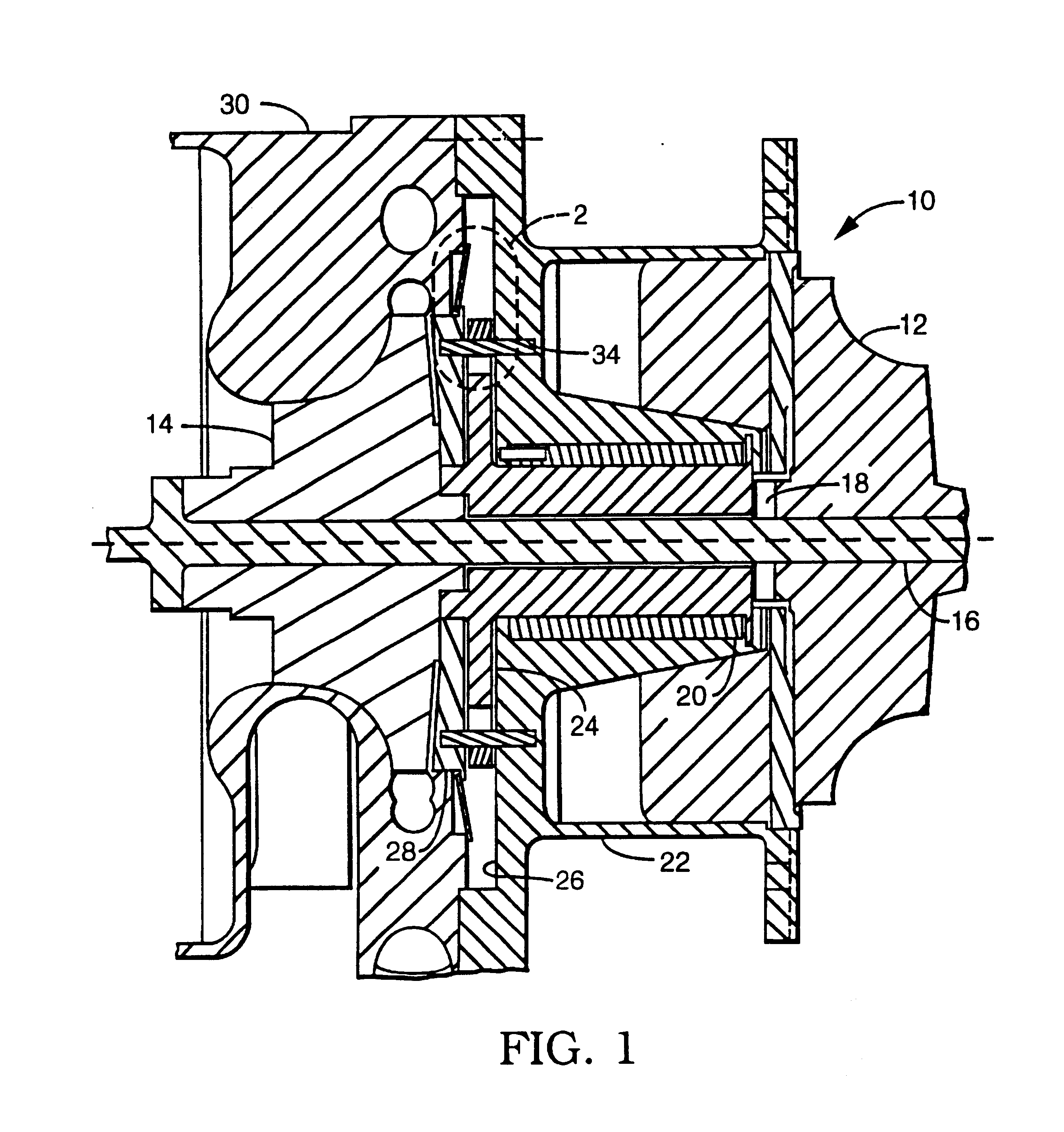
turbomachine utilizing the compliant foil fluid film thrust bearing of the present invention is illustrated in FIG. 1. The turbomachine 10 generally includes turbine wheel 12 and compressor wheel 14 at opposite ends of a common shaft or tie bar 16. The thrust and radial bearing rotor 18 is disposed around the tie bar 16 between the turbine wheel 12 and the compressor wheel 14. A journal bearing cartridge 20 in center bearing housing 22 rotatably supports the bearing rotor 18.

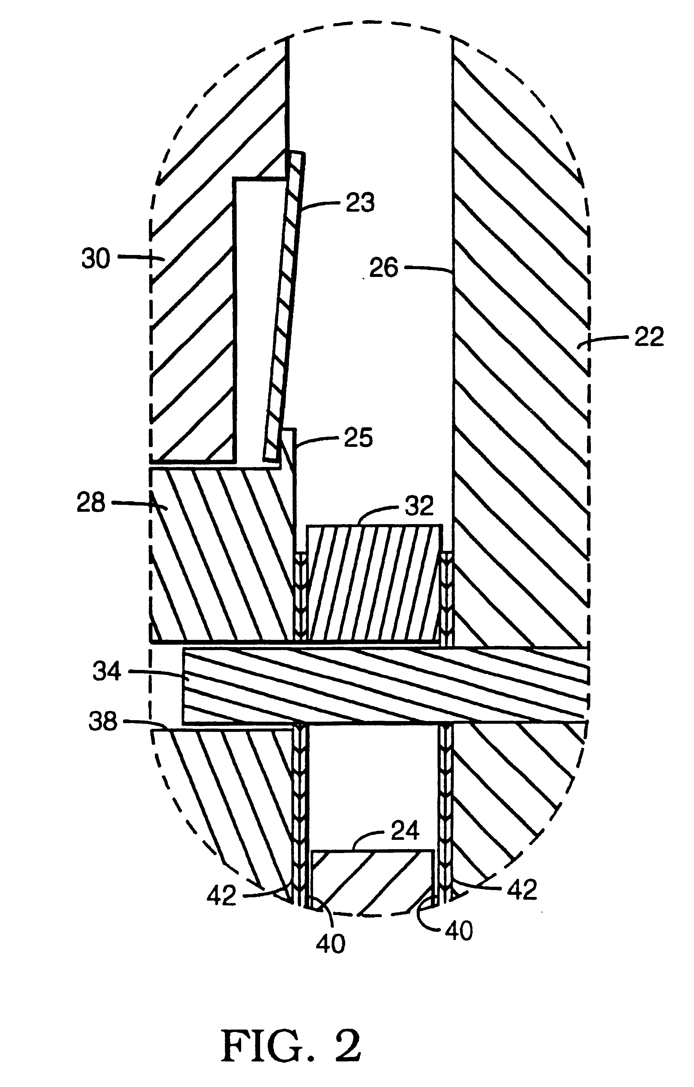
The compressor end of the bearing rotor 18 includes a radially extending thrust disk 24 which extends into a recess 26 in the compressor end of the center bearing housing 22. A bearing thrust plate 28 is disposed on the opposite side of the bearing rotor thrust disk 24. The outer periphery of the compressor end of the center bearing housing 22 engages the compressor housing 30.

As best illustrated in FIG. 2, a thrust bearing spacer 32 is positioned radially outward from the thrust disk 24 of the bearing rotor 18 ...


PUM


Abstract

A compliant foil fluid film thrust bearing including a thrust disk (24) rotor, fluid foils (40), spring foils (42), a thrust plate (28), and a housing (22) thrust surface. The non-rotating but compliant fluid foils (42), mounted on the thrust plate (28) and / or housing (22) thrust surface and positioned adjacent to the thrust disk (24), have open faced channels that induce regenerative vortex flow patterns in the process fluid. The multiple spring foils together provide a tilting pad support for the fluid folds but allow them to follow the axial and overturning motion of the thrust disk. The interaction of the tilting pad underspring supports and the circumferential fluid pressure gradients in the process fluid between the fluid foils and the thrust disk rotor assure that the fluid foils will assume hydrodynamically efficient convex shapes on the surfaces adjacent to the rotor regardless of the load applied to the thrust bearing.

Description

TECHNICAL FIELDThis invention relates to the general field of compliant foil fluid film bearings and more particularly to an improved thrust bearing employing fluid foils and multiple spring foils to support, position, damp and accommodate movements or excursions of the rotating portion of the bearing.BACKGROUND OF THE INVENTIONCompliant foil fluid film thrust bearings are currently being utilized in a variety of high speed rotor applications. These bearings are generally comprised of a two sided thrust disk rotating element, non-rotating compliant fluid foil members that axially enclose the rotating element, non-rotating compliant spring foil members that axially enclose the fluid foil members and a non-rotating thrust plate element and a non-rotating housing element that axially enclose and provide attachments for the foil members. The space between the rotating element and the thrust plate element on one side of the bearing and the space between the rotating element and the thrus...

Claims


Application Information

Patent Timeline
IPC IPC(8): F01D25/16F16C17/00F16C17/12F16C17/04F16C17/06F16C27/02
CPCF01D25/168F16C17/042F05D2240/52F05D2240/53F05D2220/40F16C2360/24F16C27/02
Inventor BOSLEY, ROBERT W.
Owner CAPSTONE TURBINE
Learn More