Ball and socket bearing for artificial joint

a technology of artificial joints and bearings, applied in the field of artificial joints, can solve the problems of patient immobility, difficult alignment of subsequent reconstructions, and inability to meet patient needs,

Inactive Publication Date: 2004-01-27
JOINT MEDICAL PROD
View PDF45 Cites 64 Cited by
  • Summary
  • Abstract
  • Description
  • Claims
  • Application Information

AI Technical Summary

Benefits of technology

In connection with both artificial hip joints and other types of ball and socket joints, it is advantageous for the surgeon to have as wide a range of joint configurations and materials to choose from as possible. It is particularly advantageous for the surgeon to be able to refine his selection of materials and configurations during the operative procedure, after he has seen the diseased joint and has a full appreciation of the patient's medical condition and anatomy. Along these same lines, it is also advantageous to be able to re-operate and change materials and/or joint configurations as a function of the patient's post-operative history without substantially disturbing the established fixation of the joint to bony structures. For example, a patient originally fitted with a semi-constrained joint may be found to be especially prone to dislocations so that a constrained construction, perhaps including a me

Problems solved by technology

Subsequent reconstructions are much more difficult to align because of deterioration of anatomical landmarks as a result of the first operation, the healing process after the operation and changes in the anatomy caused by the presence of the artificial joint.
It should be noted however, that such larger sphere sizes are not universally favored because frictional torque increases with diameter.
Such dislocations essentially make the patient immobile and can necessitate a second operation.
As discussed above, the critical alignment required for the semi-constrained construction is even more difficult to achieve when a second implantation is performed.
Unfortunately, as is apparent from the geometry of the situation, the more the socket bearing encompasses the ball, the greater the restra

Method used


Image

  • Ball and socket bearing for artificial joint
  • Ball and socket bearing for artificial joint
  • Ball and socket bearing for artificial joint

Examples


Embodiment Construction

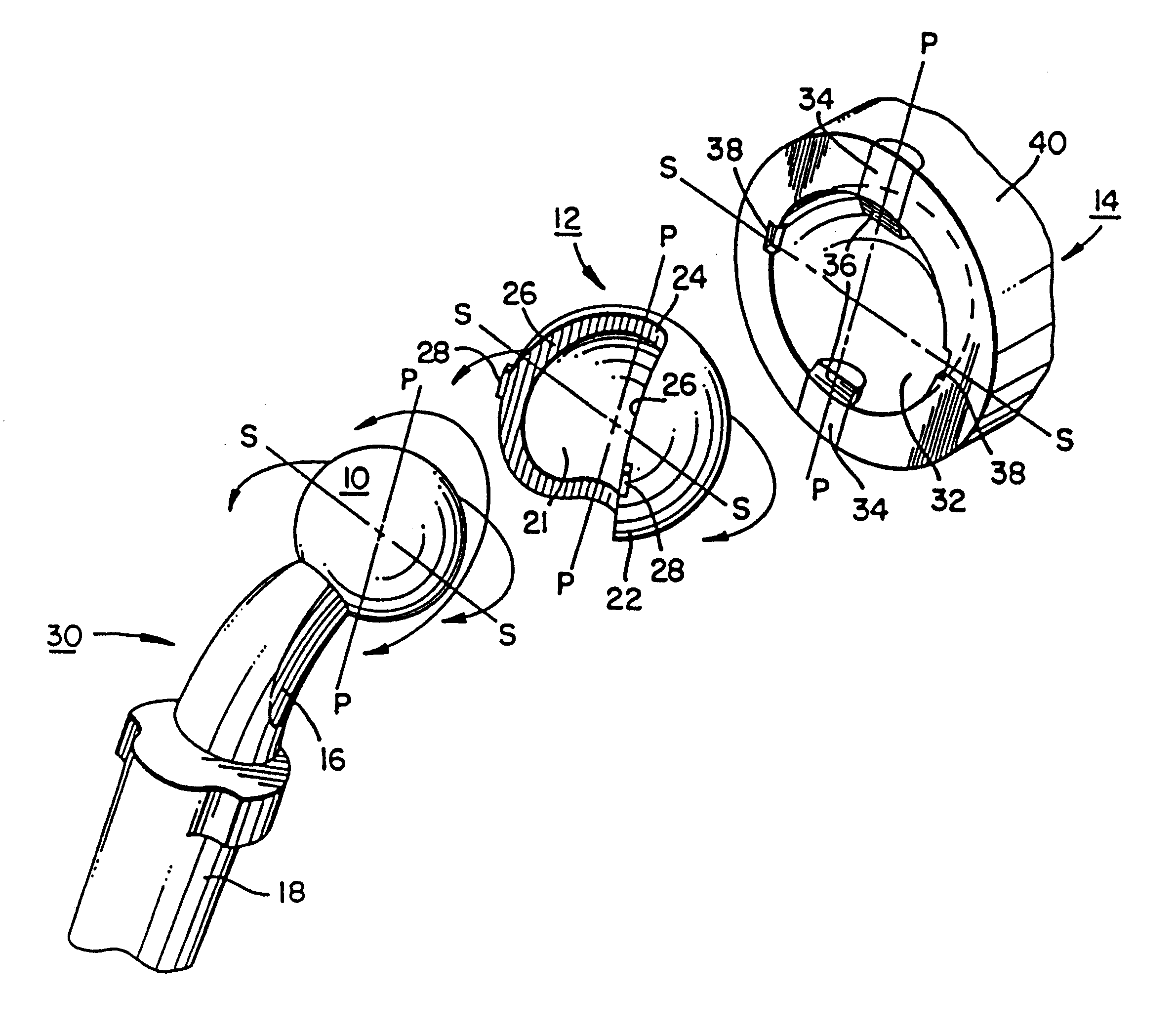
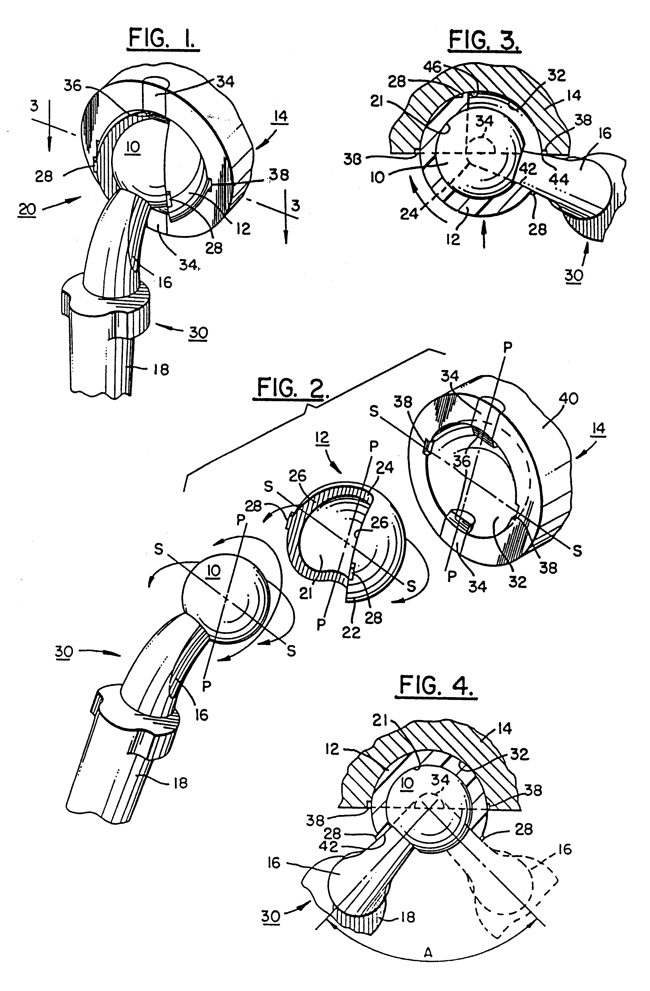
With reference now to the drawings, wherein like reference characters designate like or corresponding parts throughout the several views, there is shown in FIG. 1 an assembly 20 of ball or sphere 10, socket bearing 12 and cup 14 for a prosthetic joint. The neck 16 of arm 30 is intermediate ball 10 and stem or shaft 18, which stem or shaft is fixed to, for example, the femur bone at the time of implant surgery.

FIG. 2 shows in more detail socket bearing 12 of assembly 20. The preferred material for bearing 12 is ultra-high molecular weight polyethylene (UHMWPE). Inner spherical bearing surface 21 of bearing 12 is concentric with outer spherical bearing surface 22. Cylindrical surfaces 24 are coaxial with each other and with the center of spherical surfaces 21 and 22 and are tangent to surfaces 26. Small barb-shaped protuberances 28 serve a detent function described below.

In the plane passing through the lines P--P in FIG. 2, socket bearing 12 encompasses less than one half of ball 10....


PUM


Abstract

A ball and socket joint for implanting in the body is provided wherein the socket portion of the joint can have various orientations with respect to the patient's anatomy, and the orientation used for a particular patient can be selected and/or changed in situ, that is, during or after implantation of the joint. In addition, the configuration of the joint, e.g., constrained versus semi-constrained, as well as the materials making up the socket portion of the joint, e.g., plastic versus metal, can be selected and/or changed in situ. The questions raised in reexamination request Nos. 90/004,732, filed Aug. 26, 1997 and 90/005,596, filed Jun. 22, 1999, have been considered and the results are reflected in this reissue.

Description

BACKGROUND OF THE INVENTION1. Field Of The InventionThis invention relates to artificial joints and in particular to artificial joints of the ball and socket type.2. Description Of The Prior ArtAs is well known in the art, artificial hip and shoulder joints conventionally employ ball and socket articulations. The socket is embedded in one bony structure, for example, the pelvis for a hip reconstruction. The ball is attached to an arm composed of a neck and a stem or shaft, the stem or shaft being embedded in another bony structure, for example, the femur for a hip reconstruction.A number of methods are known for retaining the ball in the socket. In the most common method, referred to herein as the "semi-constrained" construction, the patient's own anatomy, i.e., his muscles, tendons and ligaments, are used to retain the ball within the socket. For this construction, a hemispherical socket typically is used which allows the ball and its attached arm the maximum amount of movement wit...

Claims


Application Information

Patent Timeline
IPC IPC(8): A61F2/32A61F2/00A61F2/30A61F2/34A61F2/36
CPCA61F2/32A61F2/3609A61F2002/30426A61F2002/30433A61F2002/3054A61F2002/30662A61F2002/30975A61F2002/3208A61F2002/3233A61F2002/3241A61F2002/3443A61F2002/349A61F2002/3493A61F2002/3631A61F2220/0025A61F2220/0041
Inventor NOILES, DOUGLAS G.
Owner JOINT MEDICAL PROD
Why Eureka
Try Eureka