Distributed differential coupling combined power system

Inactive Publication Date: 2006-05-02
YANG TAI HER
View PDF6 Cites 19 Cited by
  • Summary
  • Abstract
  • Description
  • Claims
  • Application Information

AI Technical Summary

Benefits of technology

[0006]The distributed differential coupling combined power distribution system of the invention may be used in driving vehicles, ships, flying machines or other mechanical, industrial, or processing equipment which require a rotational power source. The power source involves the rotational output shaft of a internal combustion engine for other rotational power sources), and is not only used to drive a front section load directly or through transmission devices such as transmission gears, belts, chains, or the couplers, but is also coupled with the input shaft of an electromagnetic coupling device to drive the rear section load. The electromagnetic coupling is a two-end structure and is respectively combined with a stator and rotor structure to be controlled by an operating device for generating motor driving functions when an input current is applied to the electromagnetic coupling device or for operating variable speed coupling functions through the output current when employed as a generator, or for use in starting the engine and as a power regeneration brake, particularly when the engine is the main transm

Problems solved by technology

In recent years, energy and noise pollution problems have become more and more serious.
A good solution to these problems would be to use electrical power driven vehicles, but development of electrical power driven vehicles has up to now been limited by the capacity of the batteries to achieve a larger moving range.
Increasing the battery volume or quantity to increase

Method used


Image

  • Distributed differential coupling combined power system
  • Distributed differential coupling combined power system
  • Distributed differential coupling combined power system

Examples


Embodiment Construction

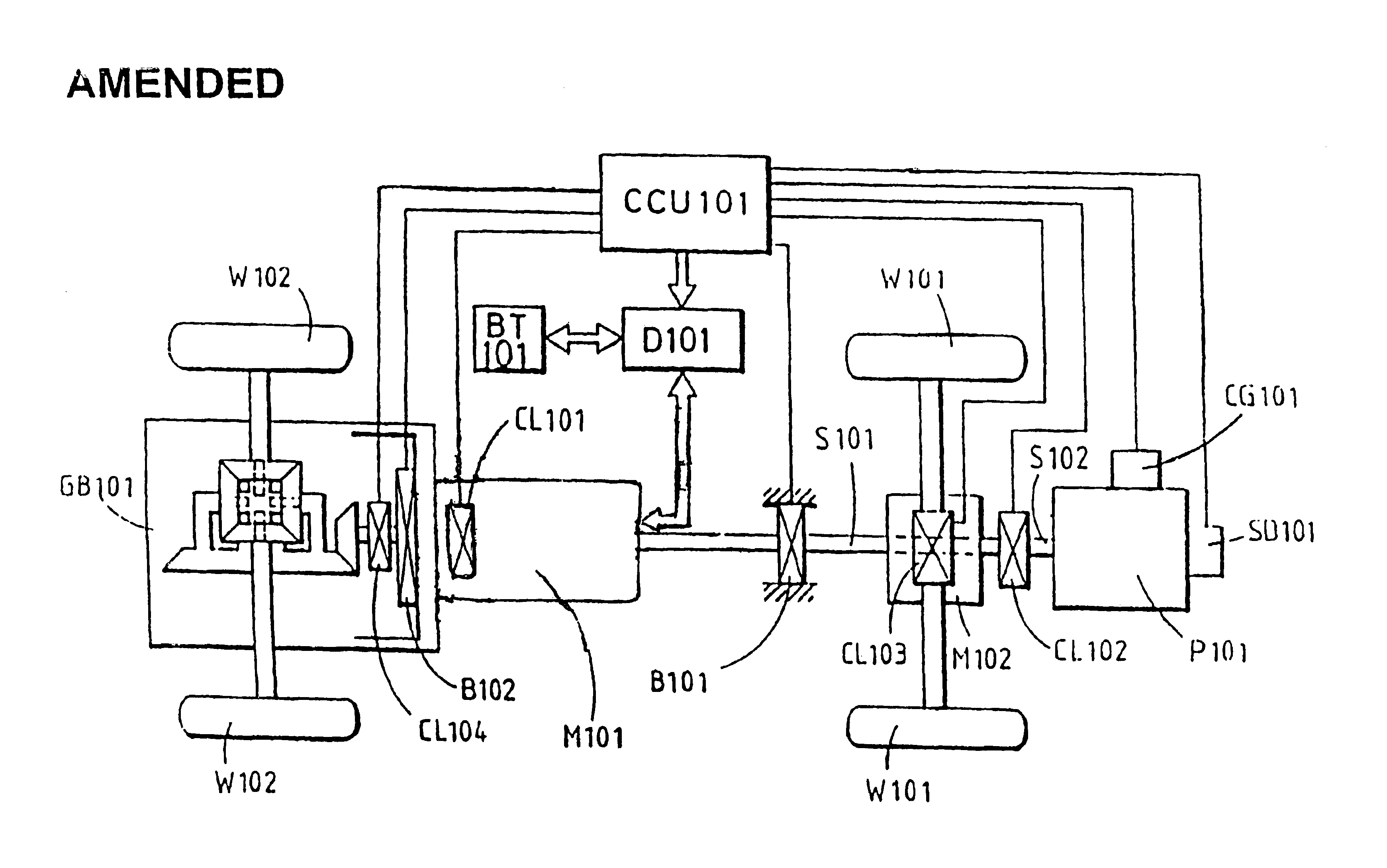
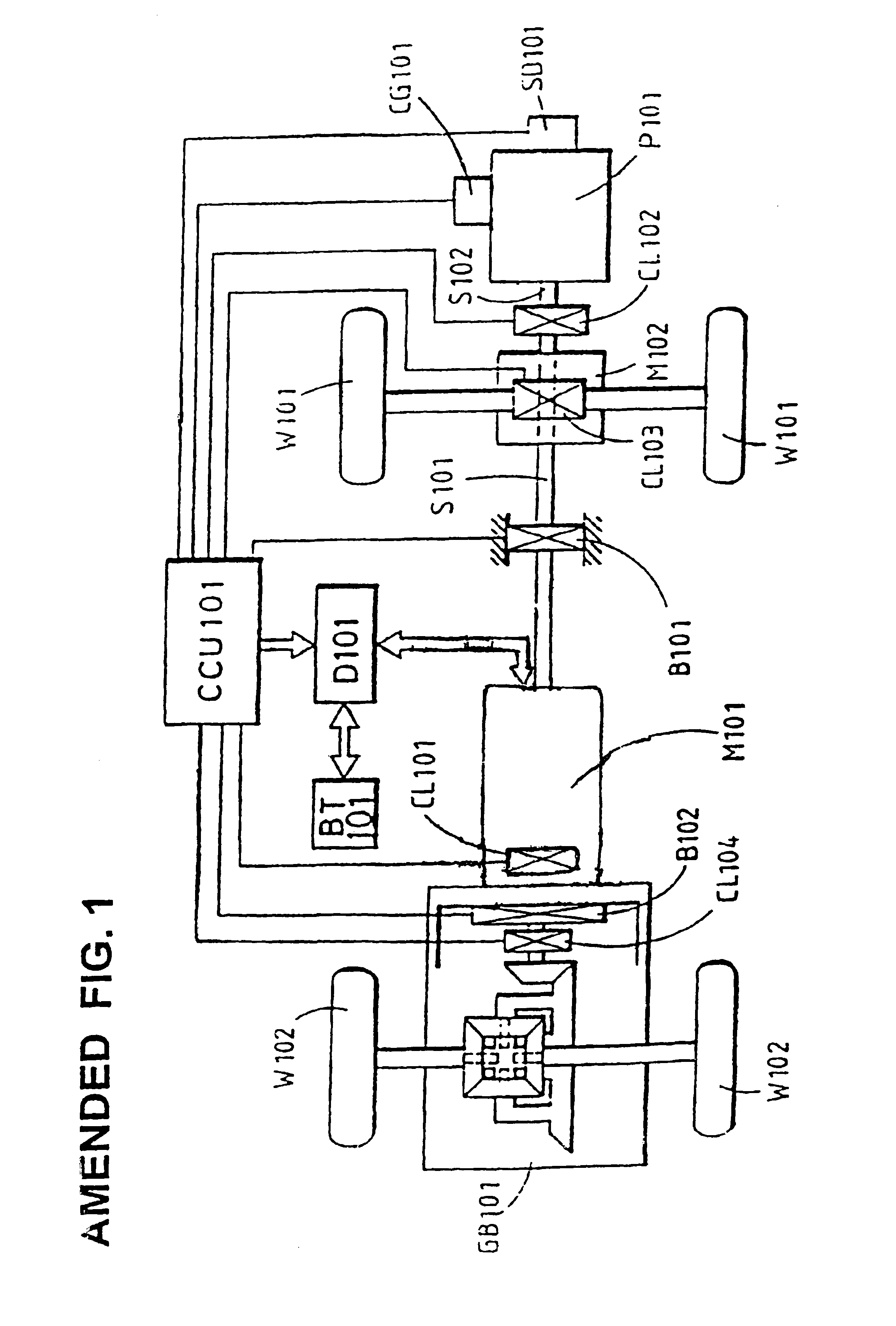
[0015]FIG. 1 shows a preferred embodiment of a distributed differential coupling combined power system, including the following principal elements:

[0016]A drive side rotational power source, having an output which is first supplied to control the front section load and then transmitted to the input end of a two-end shaft type electromagnetic coupling device to drive a rear section load.

[0017]An electromagnetic coupling device connected by a direct transmission to another load, through a transmission component to another load, or through a differential gear system to a differentially acting load such as the side rear wheels of a vehicle.

[0018]More specifically, the embodiment illustrated in FIG. 1 includes the following elements:

[0019]A drive side rotational power unit P101 in the form of an internal combustion engine or other power source, wherein the rotational output shaft S102 coupled to a middle transmission device and a control interface M102 through a clutch CL102. Engine P101...


PUM


Abstract

A combined power system includes a rotational power source such as an internal combustion engine, the output shaft of which is arranged to drive a front section load and which is also coupled to the input shaft of an electromagnetic coupling device to drive a rear section load. The electromagnetic coupling device is controlled by an operating device to generate motor driving functions, when an input current is applied or to generate variable speed coupling functions through an output current when the electromagnetic coupling device is employed as a generator. The engine can be operated at constant speed or at a partially adjustable speed to maximize engine efficiency and reduce pollution, with one part of the differential speed output power generated throughout the differential mixing drive device being used for driving the load while the remainder of the power is converted through the generator function of the electromagnetic coupling device to charge the battery and thereby increase energy efficiency.

Description

BACKGROUND OF THE INVENTION[0001]In recent years, energy and noise pollution problems have become more and more serious. A good solution to these problems would be to use electrical power driven vehicles, but development of electrical power driven vehicles has up to now been limited by the capacity of the batteries to achieve a larger moving range. Increasing the battery volume or quantity to increase the range will correspondingly increase the self-weight of the carrier, resulting in higher electrical energy consumption and does not meet economic requirements. Therefore, in the absence of a major breakthrough in solving the battery technical problems, a more practical driving method is to use combined driving structure designs. Current combined driving structure designs include:[0002](A) Series Combined Power Design: This design is the most typical structure for an electrically driven vehicle. In this design a generator is driven by the engine to generate electricity and charge the...

Claims


Application Information

Patent Timeline
IPC IPC(8): B60W10/02B60W10/00B60K6/365B60K6/40B60K6/48B60K6/52B60K17/16B60K17/356B60K23/08B60L50/15B60L50/16B60W10/06B60W10/08B60W10/26B60W20/00H02J3/28H02J7/14H02P11/00H02P15/00
CPCB60K6/40B60K6/48B60K6/52B60K17/356B60L50/15B60L50/16B60W10/06B60W10/08B60W20/00Y02T10/62Y02T10/70Y02T10/7072Y10S903/916Y10S903/951B60K6/365B60K17/16B60K23/08B60K2006/262B60L2240/441B60W10/02B60W10/26B60W2510/0638B60W2710/0605B60W2710/0644Y10S903/91Y10S903/946B60K17/02B60K17/35B60K23/0808B60K1/00B60K2001/001B60L2240/421B60L2240/429B60L7/10B60L50/61B60K2006/268Y02T10/64B60W20/10B60K6/445
Inventor YANG, TAI-HER
Owner YANG TAI HER
Why Eureka
Try Eureka