Method of using a water transport plate

a technology of water transport plate and water permeability, which is applied in the direction of sustainable manufacturing/processing, final product manufacturing, electrochemical generators, etc., can solve the problems of high cost of manufacture, limited strength, and difficult to achieve the solution of water management and cell cooling in ion-exchange membrane fuel cell power plants, etc., to achieve optimal pore size, resistivity and yield strength, and optimal balance of bubble pressure and water permeability

Inactive Publication Date: 2006-10-17
AUDI AG
View PDF22 Cites 4 Cited by
  • Summary
  • Abstract
  • Description
  • Claims
  • Application Information

AI Technical Summary

Benefits of technology

[0014]It is also an object of the present invention to provide a water transport plate which has a construction with an optimal balance of bubble pressure and water permeability.
[0015]It is further an object of the present invention to provide a water transport plate which has optimal pore size, open porosity, resistivity and yield strength.

Problems solved by technology

These systems are serviceable, but are relatively complex.
One problem occurring in solid polymer fuel cells relates to the management of water, both coolant and product water, within the cells in the power plant.
The aforesaid solution to water management and cell cooling in ion-exchange membrane fuel cell power plants is difficult to achieve due to the quality control requirements of the fine and finer pore plates, and is also expensive because the plate components are not uniformly produced.
Due to the constraints of the water transport plate formation process, these plates are costly to manufacture and possess limited strength.
Although this is a common water transport plate formation process, the forming speed is slow and it is difficult to incorporate relatively long fibers which are desirable for water transport plate structural integrity.
This fiber bundling, which corresponds to uneven fiber distribution, creates weak areas within the composite which are susceptible to structural failure.
Consequently, the tolerances in the specification for the water transport plate are small and the fabrication is difficult, resulting in many rejected parts.

Method used


Image

  • Method of using a water transport plate
  • Method of using a water transport plate

Examples


example 1

[0037]The following process can be utilized to form a 40 wt % AirCo 90 graphite powder, 5 wt % FORTAFIL ½ inch unsized carbon fiber, 28 wt % OXYCHEM Phenolic resin, and 27 wt % Softwood Pulp.

1. Water is mixed with the solids in a portion of 0.4 g graphite powder, 0.05 g carbon fibers, 0.28 g Oxy-Chem Phenolic Resin, and 0.27 g Softwood Pulp to form a slurry having about 1 v / o solids.

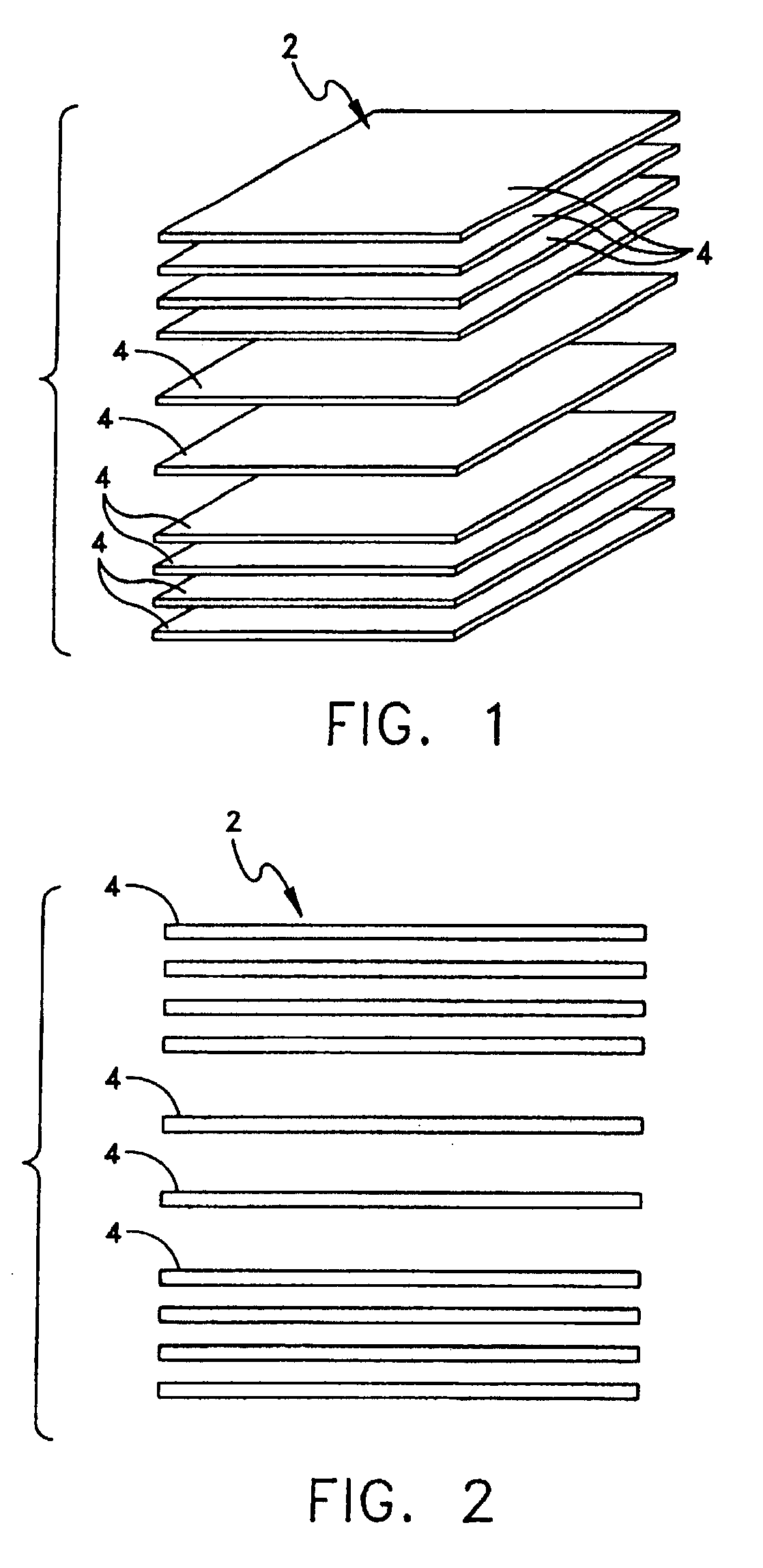
2. Once thoroughly blended, the slurry is showered onto a horizontally moving screen to form a planar sheet with a basis weight of 250 lb. / ream or 12 oz / sq.-yard, plus or minus 5%.

3. The screen is passed over a vacuum to remove some of the remaining water, and thereby partially dry the planar sheet.

4. The partially dried planar sheet is then directed over rollers and oil heated drums to volatilize residual water and form the dried paper. The drums are heated to 250° F.

5. The dried paper is spooled on a cardboard tube for collection.

6. The spooled paper is cut into 10-12 inch by 6 inch sheets.

7. The sheet...


PUM

PropertyMeasurementUnit
pore sizeaaaaaaaaaa
compressive yield strengthaaaaaaaaaa
pressureaaaaaaaaaa

Abstract

A water transport plate is provided with optimized physical characteristics to greatly improve fuel cell operation. In a preferred method of manufacturing, graphite powder, reinforcing fibers, cellulosic fibers, and a thermosetting resin are mixed with a liquid to form a slurry and showered onto a screen to form a planar sheet which is dried to form paper. The paper is cut into the desired size and is laid-up. The lay-up is laminated with pressure and heat, carbonized, and graphitized to form a water transport plate for later machining as desired. The finished water transport plate exhibits optimal physical characteristics for bubble pressure, water permeability, median pore size, porosity, thru-plane resistivity and compressive yield strength.

Description

BACKGROUND OF THE INVENTION[0001]The present invention relates to water transport plates. More specifically, the present invention relates to water transport plates and a method of use thereof.[0002]Solid polymer electrolyte fuel cell power plants are known in the prior art, and prototypes are even available from commercial sources, such as Ballard Power Systems, Inc. of Vancouver, Canada. These systems are serviceable, but are relatively complex. An example of a Ballard Power Systems polymer membrane power plant is shown in U.S. Pat. No. 5,360,679, granted Nov. 1, 1994. One problem occurring in solid polymer fuel cells relates to the management of water, both coolant and product water, within the cells in the power plant. In a solid polymer membrane fuel cell power plant, product water is formed by an electro-chemical reaction on the cathode side of the cells, specifically by the combination there of hydrogen ions, electrons and oxygen molecules. The product water must be drawn awa...

Claims


Application Information

Patent Timeline
Patent Type & Authority Patents(United States)
IPC IPC(8): H01M8/00H01M8/02H01M8/04H01M8/10
CPCH01M8/02H01M8/0234H01M8/026H01M8/04029H01M8/04119H01M8/04156H01M2300/0082Y02P70/50Y02E60/50
Inventor GORMAN, MICHAEL E.
Owner AUDI AG
Why Eureka
Try Eureka