Method and apparatus for mixing fluids

a technology of fluid mixing and apparatus, applied in water cleaning, filtration separation, separation processes, etc., can solve the problems of reducing the level of hydrogen sulfide gas, releasing sulfides from sewage, and sewage contains a significant amount of potentially volatile dissolved molecular hydrogen sulfide, so as to reduce the gas emission of fluid

Inactive Publication Date: 2008-07-01
VORTEX FLOW
View PDF55 Cites 23 Cited by
  • Summary
  • Abstract
  • Description
  • Claims
  • Application Information

AI Technical Summary

Benefits of technology

[0009]It, therefore, is an object of this invention to provide a method for reducing gas emissions of a fluid through the entraining and mixing of gas with the liquid.

Problems solved by technology

One problem that occurs during the transport of sewage is the release of sulfides from the sewage.
Unfortunately, in most practical applications, sewage contains a significant amount of potentially volatile dissolved molecular hydrogen sulfide gas.
Thus, while drop structures can reintroduce dissolved oxygen into the sewage flow, lowering the level of hydrogen sulfide gas, they can also cause the release of hydrogen sulfide gas.
The hydrogen sulfide emissions often cause corrosion with the drop structures and adjacent sewer lines, and cause odor problems even the most elegant, pristine neighborhoods.
Two problems remain to be solved when applying this known method of using a vortex form in a drop structure for sewage flows.
First, the upstream flow velocities within the influent line are usually not large enough to create a stable spiral flow on the vertical wall of a typical maintenance hole.
Thus, the flow, rather than continuing to spiral down the cylindrical wall of the maintenance hole, will generally revert to a turbulent descending flow similar to waterfall, losing the effective energy dissipation of the spiral flow and releasing significant amounts of hydrogen sulfide gas into the air.
Second, quite often the maintenance hole is used for additional lateral influent connections at elevations lower than the main influent pipe.
Consequently, the lateral influent connections disrupt the spiral flow and create a turbulent waterfall of sewage to the bottom of the maintenance hole, again releasing significant amounts of hydrogen sulfide gas into the air.

Method used


Image

  • Method and apparatus for mixing fluids
  • Method and apparatus for mixing fluids
  • Method and apparatus for mixing fluids

Examples


Embodiment Construction

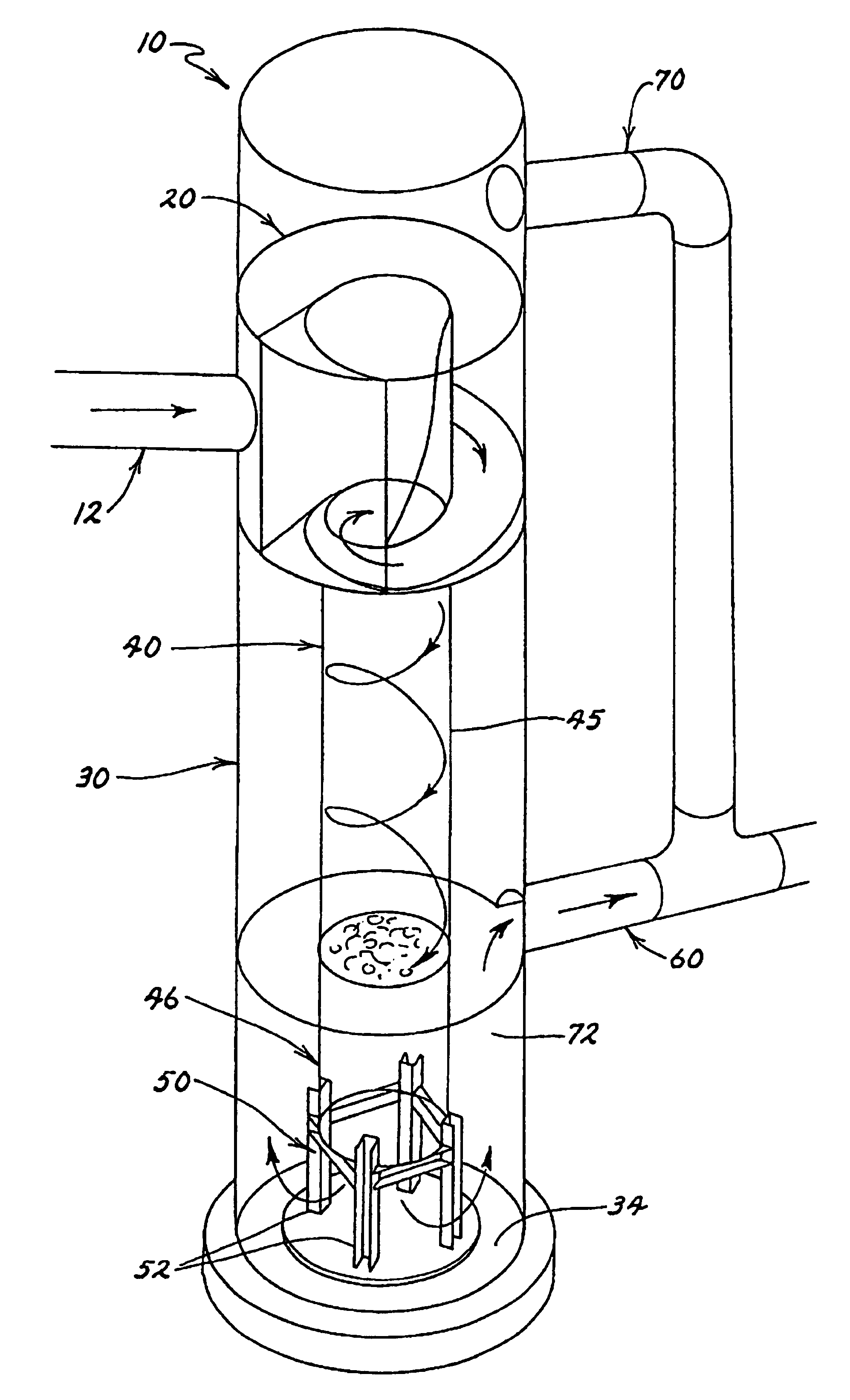
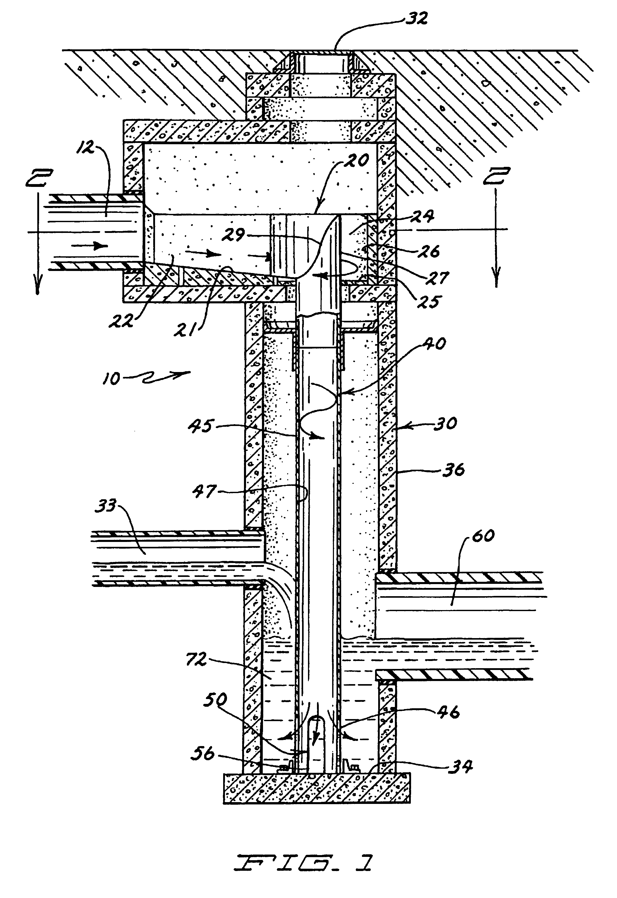
[0030]FIG. 1 illustrates in a side elevation view one embodiment of a sewer apparatus 10 constructed in accordance with the present invention. Referring to FIG. 1, the sewer apparatus 10 includes an influent line 12, a vortex form 20, a maintenance hole 30, a conduit 40, a flow exit 50, and an effluent line 60.

[0031]The maintenance hole 30 in which the vortex form 20 is disposed may be identified from street level as being below a manhole cover 32. FIG. 1 shows the maintenance hole 30 as being cylindrical in shape and oriented vertically. A lateral line 33 for inputting additional city sewer flowage into the maintenance hole 30 may be disposed below the influent line 12. The base 34 and walls 36 of the maintenance hole 30 are generally concrete. An energy dissipating pool 72, comprised of sewage, forms at the base 34 of the maintenance hole 30. An effluent line 60 is connected to the maintenance hole 30 near the top level of the energy dissipating pool 72.

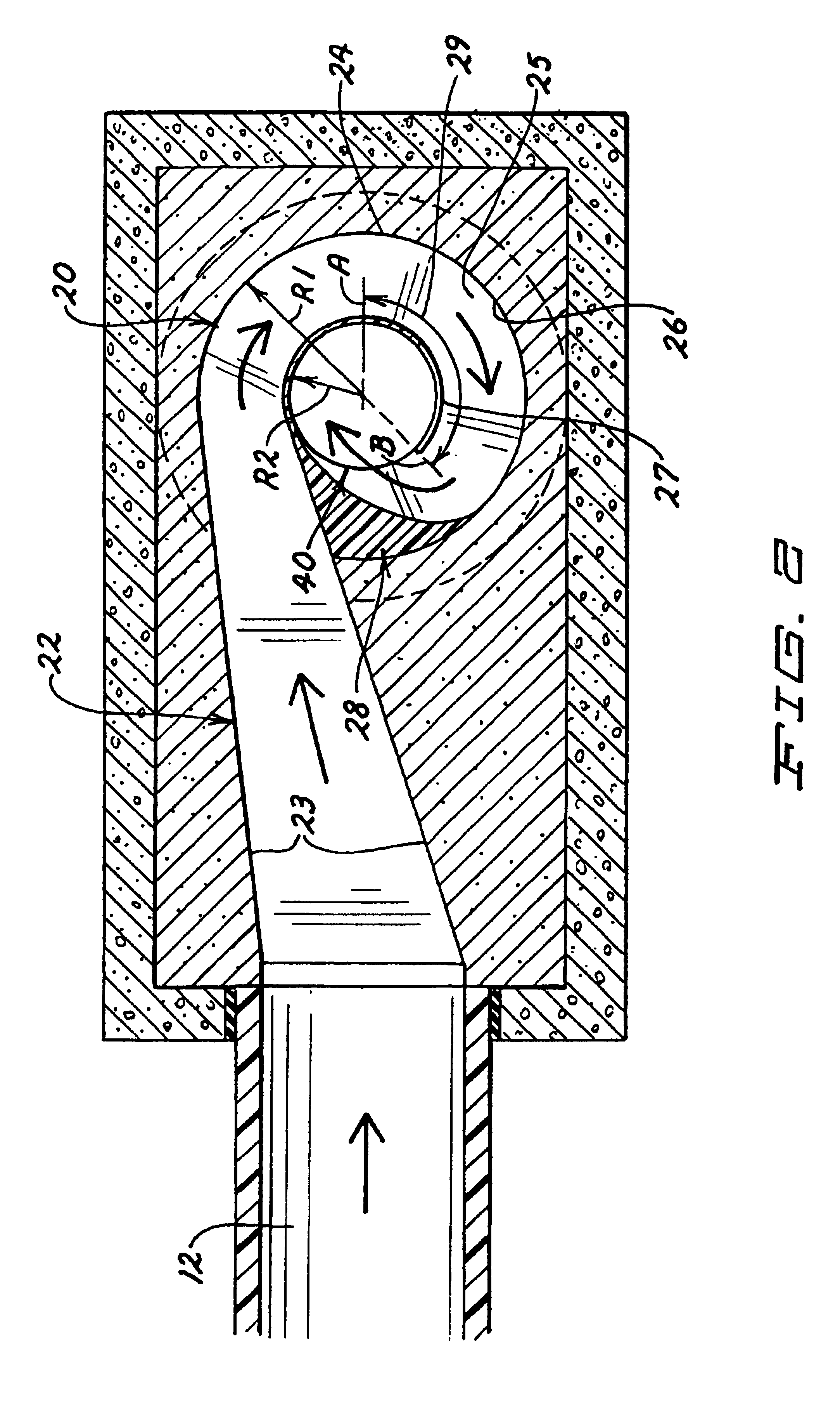
[0032]As illustrated in FIG...


PUM

PropertyMeasurementUnit
velocityaaaaaaaaaa
outer radiusaaaaaaaaaa
inner radiusaaaaaaaaaa

Abstract

A method for entraining and mixing gas with liquids within a conduit or drop structure, comprising the channeling of one or more liquid flows into spiral flows of predetermined radius (radii), reducing the predetermined radius (radii) to increase the centrifugal forces acting upon the spiral flow(s) as the spiral flow(s) enter the conduit, and allowing gas access to the conduit to mix with and entrain within the spiral flow within the conduit or drop structure. The method can facilitate the mixing of gas with one or more fluid flows and/or reduce the release of gas emissions from the fluid(s) into the surrounding environment.

Description

[0001]This application claims the benefit ofis a continuation-in-part <?insert-end id="INS-S-00001" ?>of U.S. patent application Ser. No. 09 / 561,999 filed May 1, 2000, now U.S. Pat. No. 6,419,843 <?insert-start id="INS-S-00002" date="20080701" ?>B2 <?insert-end id="INS-S-00002" ?>which claimed the benefit of provisional patent application No. 60 / 135,476 filed May 24, 1999.FIELD OF USE[0002]The invention relates generally to applications whereby it is desirous to introduce or reintroduce gas with liquid flowing through pipes, and / or mix two fluids within a pipe. In particular, this method can be used, but is not so limited, to mix and entrain air and other odorous gas emissions into sewage to reduce odorous gas emissions and to reduce hydrogen sulfide corrosion and abrasive wear in waste water conveyance, collection and treatment systems.BACKGROUND OF THE INVENTION[0003]Throughout past decades, sewers have been utilized to efficiently transport waste water or sewag...

Claims


Application Information

Patent Timeline
Patent Type & Authority Patents(United States)
IPC IPC(8): B01D21/26C02F1/72E03F5/00
CPCC02F1/74E03F3/04E03F5/08C02F2303/02C02F2303/08B01F23/2323B01F23/23412B01F2025/913B01F25/102
Inventor NATARIUS, EUGENE M.
Owner VORTEX FLOW
Why Eureka
Try Eureka