Methods and apparatus for providing touch-sensitive input in multiple degrees of freedom

a technology of input control and multiple degrees of freedom, applied in the field of input control devices with multiple surfaces, can solve the problems of user fatigue, cumbersome 3d and 6d input devices, and inability to refine, improve accuracy, and ease of use of existing 2d input devices,

Inactive Publication Date: 2009-09-01
SANDIO TECH
View PDF61 Cites 159 Cited by
  • Summary
  • Abstract
  • Description
  • Claims
  • Application Information

AI Technical Summary

Benefits of technology

[0014]An input controller of the present invention incorporates multiple force / touch sensitive input elements and provides intuitive input in up to 36 degrees-of-freedom, including position and rotation, in either a Cartesian, cylindrical or spherical coordinate system. Input can be provided in the provided degrees of freedom without requiring movement of the controller, so that the controller is suitable for controlling both cursors or other computer objects in an interactive computer system and for controlling equipment such as heavy cranes and fork lift trucks.

Problems solved by technology

However, current 3D and 6D input devices do not exhibit the refinement, accuracy or ease of use characteristic of existing 2D input devices.
In fact, existing 3D / 6D input devices are typically cumbersome, inaccurate, non-intuitive, tiring to use, and limited in their ability to manipulate objects.
However, the user is required to wear a bulky and awkward glove and movement of these awkward controllers in free space is tiring.
Further, these devices are typically affected by electromagnetic or acoustic interference, and they are limited in their ability to manipulate objects because of the inherent dissimilarity between the free-form movement of a glove and the more constrained movement of manipulated objects.
However, it is affected by the presence of metals and also requires manipulating the controller in free space.
However, all “flying mouse” devices require the undesirable and tiring movement of the user's entire arm to manipulate the controller in free space.
Further, these devices are either tethered by a cord or sensitive to either electromagnetic or acoustic noise.
This device is a 6D controller using 6 independent accelerometers in an “inertial mouse.” However, the device must still be moved in space, and the use of accelerometers rather than ranging devices limits the accuracy.
However, these devices are subject to a number of disadvantages.
For example, it is difficult to provide for precise positioning, as there is no provision for the use of a stylus.
Further still, these devices provide for only relative control and have no provision for providing an absolute origins or an absolute positions.
They are therefor not suitable for providing closure in digitized 3D inputs.
Finally, they are limited in their ability to provide an intuitive feel for 3D manipulation of a controlled object not specified in the Cartesian coordinate system.
For example, they are not readily adaptable to spherical or cylindrical coordinate systems.
However, these devices are currently limited in manipulating objects beyond 2.5 dimensions, i.e. X-position, Y-position, and positive Z-direction, and are not available in any intuitive controllers.
However, these devices do not typically provide for 3D / 6D inputs.
However, this device does not provide inputs for roll, yaw or pitch, and does not provide any input for a negative Z input (i.e. there is no input once the stylus is lifted).
Thus, it is limited in its ability to provide 3D positioning information, as this would require an undesirable bias of some sort.
Accordingly, many input control devices used for interactive computer graphics are not suitable for use in field applications.
This poor user interface requires the operator to select and select and pull one of a number of levers corresponding to the boom rotation control to cause the boom to rotate to the left.
Such non-intuitive controls makes training difficult and time-consuming and increases the likelihood of accidents.

Method used


Image

  • Methods and apparatus for providing touch-sensitive input in multiple degrees of freedom
  • Methods and apparatus for providing touch-sensitive input in multiple degrees of freedom
  • Methods and apparatus for providing touch-sensitive input in multiple degrees of freedom

Examples


first embodiment

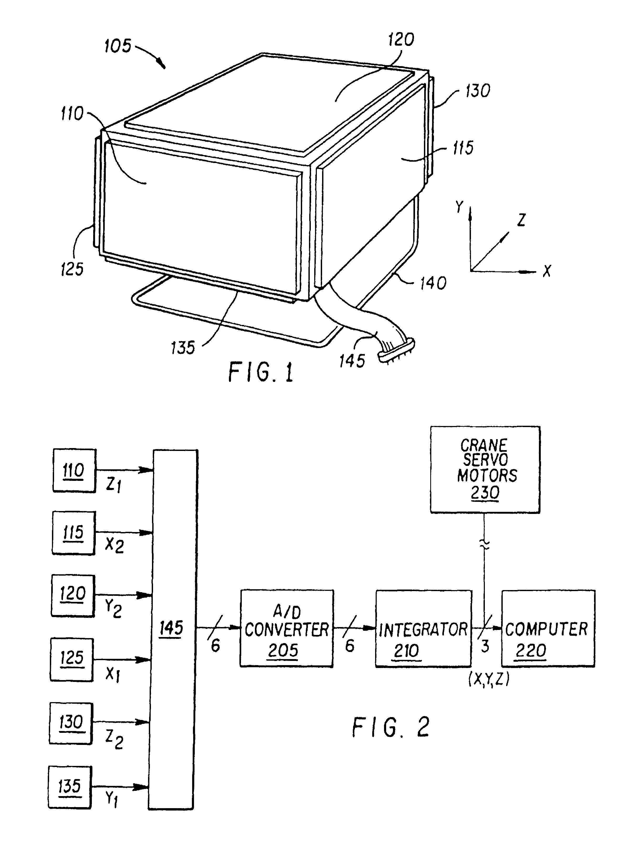
[0116]FIG. 1 is an illustration of a force / touch sensitive 3D controller in accordance with the present invention. A controller 105 is shaped substantially in the form of a cube having six faces or sides, i.e. controller 105 can be provided as a cube shape or other similar shapes, such as a rectilinear object or cube having rounded edges or the like. Alternatively, controller 105 can have other shapes. A first force-sensitive sensor pad 110 is positioned on the front face of controller 105. A second force-sensitive sensor pad 115 is positioned on the right side of controller 105. A third force-sensitive sensor pad 120 is positioned on the top side of controller 105. A fourth force-sensitive sensor pad 125 is positioned on the left side of controller 105. A fifth force-sensitive sensor pad 130 is positioned on the back side of controller 105. A sixth force-sensitive sensor pad 135 is positioned on the bottom side of controller 105. A frame 140 is attached to the edge of controller 10...

second embodiment

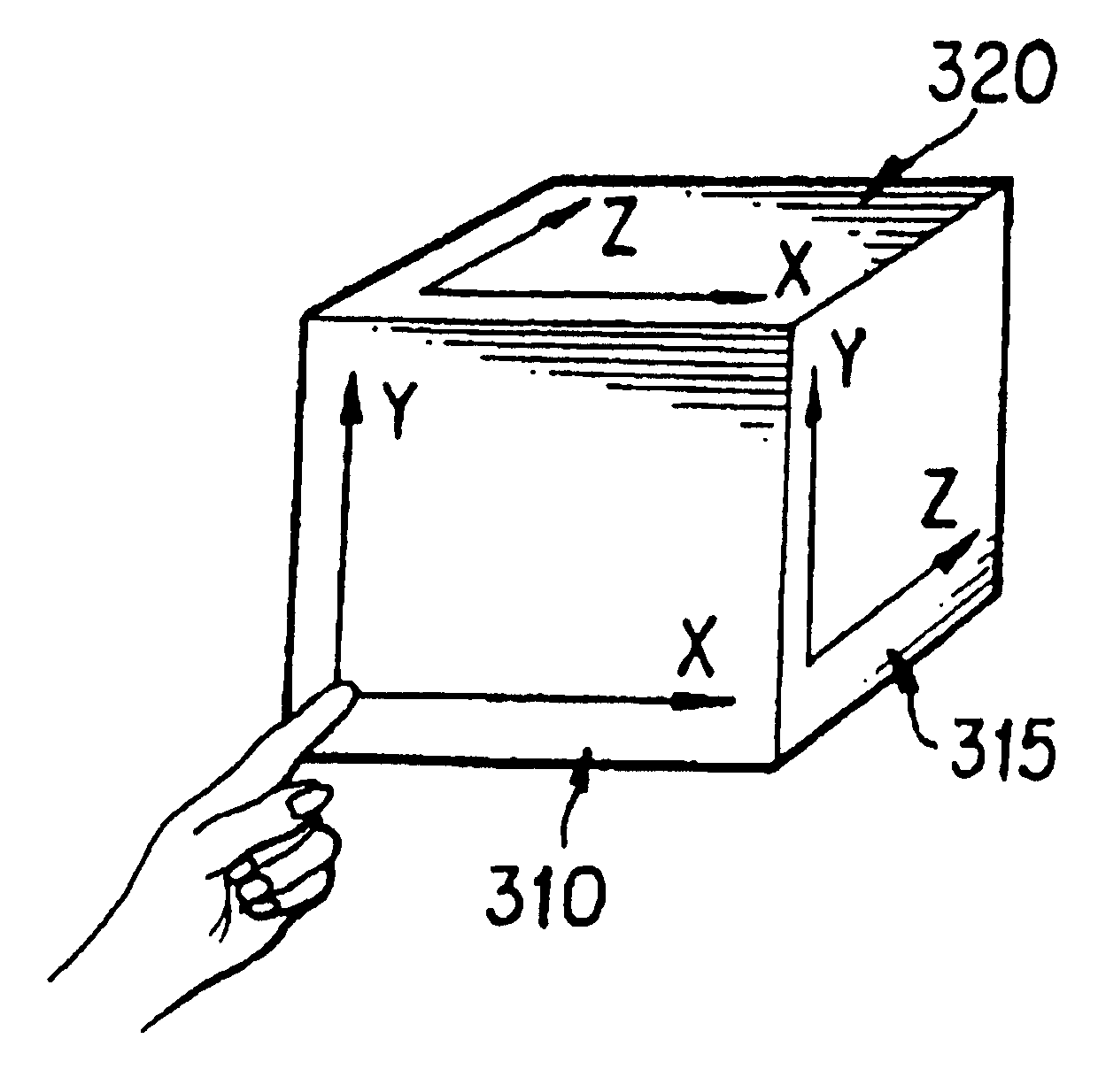
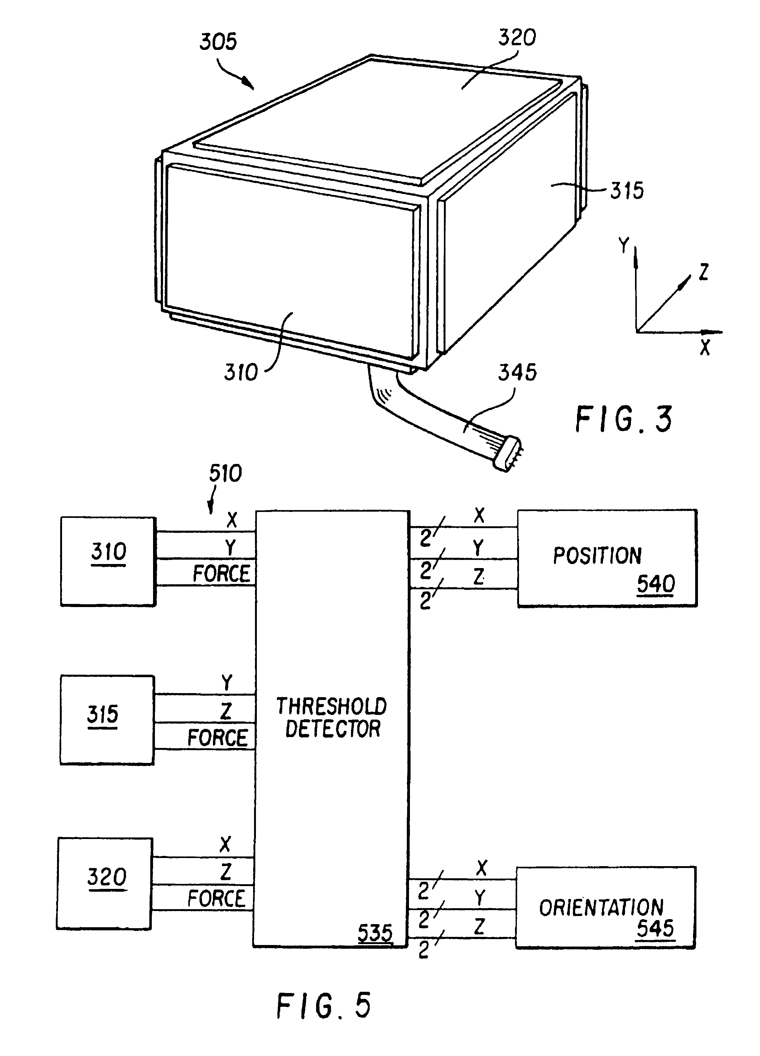
[0122]FIG. 3 is an illustration of a force / touch sensitive 6D controller in accordance with the present invention. Controller 305 is also shaped in the form of a cube, however this controller uses three force-sensitive matrix sensors. A first force-sensitive matrix sensor 310 is positioned on the front of controller 205. Sensor 310 provides two analog signals in response to the position of an applied force, which provides X and Y position information as illustrated in FIG. 4a. Sensor 310 also provides a third signal is response to the magnitude of the force applied to sensor 310. A second force-sensitive matrix sensor 315 is positioned on the right side of controller 305. Sensor 315 provides two analog signals in response to the position of the force applied to sensor 315, which will be interpreted by control electronics to provide Y and Z information as illustrated in FIG. 4a. Sensor 315 also provides a third signal responsive to the magnitude of the force applied to sensor 315. A ...

third embodiment

[0127]FIG. 6 illustrates a 6D controller 605. Controller 605 is shaped substantially in the form of a cube. A first force-sensitive matrix sensor 610 is positioned on the front of controller 605. A second force-sensitive matrix sensor 615 is positioned on the right side of controller 605. A third force-sensitive matrix sensor 620 is positioned on the top side of controller 605. A fourth force-sensitive matrix sensor 625 is positioned on the left side of controller 605. A fifth force-sensitive matrix sensor 630 is positioned on the back side of controller 605. A sixth force-sensitive matrix sensor 635 is positioned on the bottom side of controller 605. A frame 640 is attached to the edge of controller 605 between the bottom and back surfaces, allowing the user to access to all six surfaces of controller 605. Control harness 645 is coupled to force-sensitive matrix sensor 610, 615, 620, 625, 630, and 635 and provides signals indicative of the magnitude and the position of the force ap...


PUM


Abstract

Disclosed is a multiple coordinate controller device having a three-dimensional body with a first surface portion and a second surface portion where the second surface portion is not coplanar with the first surface. A first transducer with a first sensing surface is coupled to the first surface portion of the body and capable of detecting both positions and a range of pressure forces at positions on the first sensing surface. The first transducer is further capable of providing a first range of z coordinates at a detected x,y coordinate in response to the range of pressure forces on said first sensing surface. A second transducer having a second sensing surface is coupled to the second surface portion of the body and capable of detecting both positions and a range of pressure forces at the positions on the second sensing surface. The second transducer is further capable of providing a second range of z coordinates of opposite polarity to the first range of z coordinates in response to the range of forces on second sensing surface.

Description

CROSS REFERENCE TO RELATED APPLICATIONS[0001]The present application is a continuation-in-part of U.S. patent application Ser. No. 08 / 696,366 filed on Aug. 13, 1996, now abandoned which is a continuation-in-part of U.S. patent application Ser. No. 08 / 509,797 filed on Aug. 1, 1995, now U.S. Pat. No. 5,729,249, which is a continuation of U.S. patent application Ser. No. 08 / 238,257 filed on May 3, 1994, now abandoned, which is a continuation-in-part of U.S. patent application Ser. No. 07 / 798,572 filed on Nov. 26, 1991, now U.S. Pat. No. 5,335,557, all of which are incorporated herein by reference. The present application also claims the benefit of U.S. Provisional Application No. 60 / 086,036, filed May 19, 1998, which is incorporated herein by reference.BACKGROUND OF THE INVENTION[0002]1. Field of the Invention[0003]The present invention relates to the field of input control devices. More specifically, it relates to force-sensitive input-control devices with multiple surfaces capable of...

Claims


Application Information

Patent Timeline
Patent Type & Authority Patents(United States)
IPC IPC(8): G08C21/00G06F3/033G06F3/048
CPCA63F2300/1068G06F3/0338G06F3/03543G06F3/03547G06F3/0362G06F3/0488G06V30/228
Inventor YASUTAKE, TAIZO
Owner SANDIO TECH
Why Eureka
Try Eureka