
Impedance matching device for broad band impulse signal ground penetrating radar

An impedance matcher and ground penetrating radar technology, which can be used in instruments, re-radiation, electromagnetic wave detection, etc., can solve problems such as difficult processing, achieve good impedance gradient, reduce production costs, and improve the effect of signal-to-noise ratio.

Inactive Publication Date: 2007-08-29
粟毅
View PDF3 Cites 1 Cited by
  • Summary
  • Abstract
  • Description
  • Claims
  • Application Information

AI Technical Summary

Problems solved by technology

If a medium with continuously changing impedance is used, although the impedance matching between the air and the ground can be better achieved, such a medium is difficult to process

Method used


Image

  • Impedance matching device for broad band impulse signal ground penetrating radar
  • Impedance matching device for broad band impulse signal ground penetrating radar
  • Impedance matching device for broad band impulse signal ground penetrating radar

Examples


Embodiment Construction

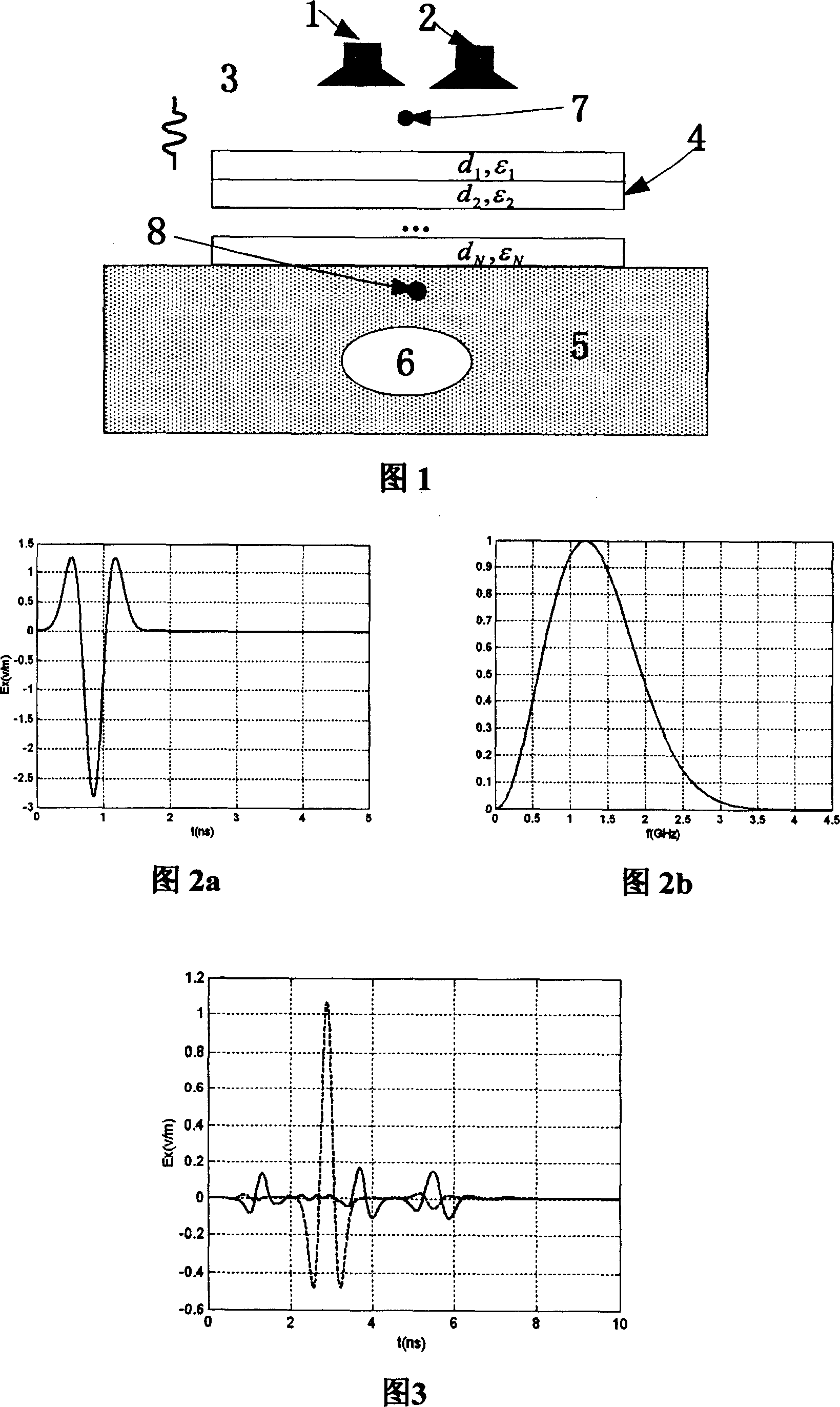
[0018] In order to couple the energy emitted by the ground penetrating radar system to the ground as much as possible and improve the efficiency of the system, the present invention provides a ground penetrating radar layered medium-loaded impedance matcher, which can reduce the reflected waves of the ground to a large extent. Conducive to the detection and identification of underground targets. The present invention includes a transmitting antenna 1 and a receiving antenna 2. A dielectric plate 4 is arranged above the soil area 5, and the dielectric plate 4 has multiple layers.

[0019] According to the theory of transmission line, for the dielectric plate 4 whose actual thickness d is infinite, its transfer matrix is:

[0020] M n = x iZ cn * 1 ...


PUM


Abstract

The invention relates to a wide band impulse signal detect radar induction reform. It comprises transmitting aerial, receiving aerial, wherein medium plate which is inductivity graded multilayer is posited on the top of soil area, the layered medium which formed wide band impulse signal detect radar is loading induction reform.

Description

technical field [0001] The invention relates to an impedance matching device for a broadband pulse signal ground penetrating radar. Background technique [0002] Ground penetrating radar (GPR) is one of the most promising and promising methods in the non-destructive detection technology of various underground shallow targets. It is mainly used in non-destructive testing of roads, bridges, tunnels, buildings and mines, geological exploration and research, as well as the detection, location and identification of various metal and non-metal targets such as underground pipelines, mines, and unexploded ordnance (UXO). In these applications, due to the discontinuity of impedance between the space where the antenna is located and the ground, during the transmission process of electromagnetic waves fed into the ground by the antenna, a large energy reflection is caused on the ground surface, resulting in the reduction of electromagnetic wave energy entering the ground. Moreover, th...

Claims


Application Information

Patent Timeline
Patent Type & Authority Patents(China)
IPC IPC(8): G01V3/12G01S7/02G01S13/02
Inventor 粟毅黄春琳刘立业
Owner 粟毅
Learn More