Continuous preparation facilities for casting semisolid blank made from alloy in lightweight
A light alloy and preparation device technology, applied in the direction of metal extrusion dies, etc., can solve the problems of uneven microstructure of the billet, coarse grains of the billet, low degree of spheroidization, etc., and achieve uniform microstructure, high degree of spheroidization, The effect of low manufacturing cost
- Summary
- Abstract
- Description
- Claims
- Application Information
AI Technical Summary
Problems solved by technology
Method used
Image
Examples
specific Embodiment approach 1
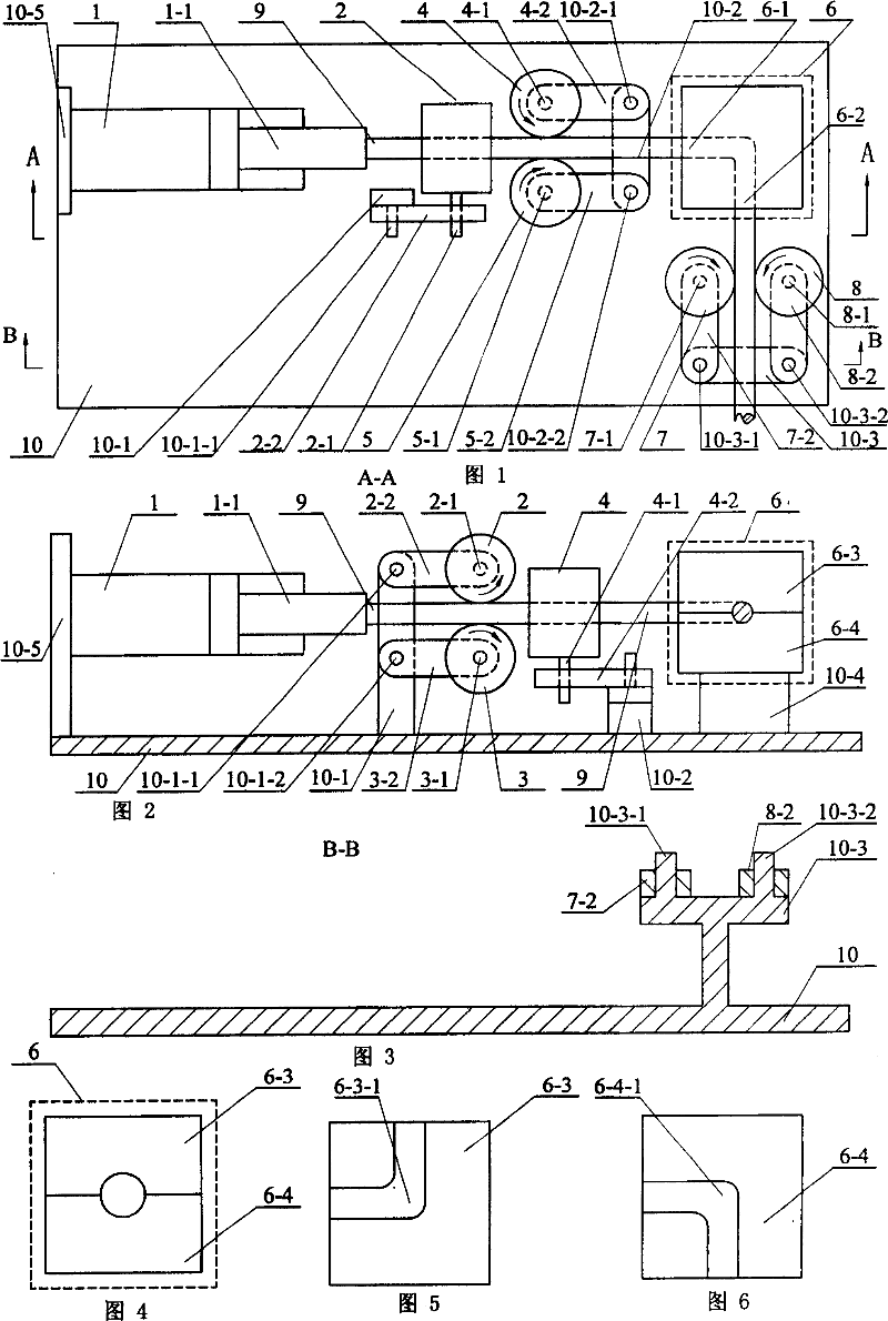
[0012] Embodiment 1: This embodiment is described in conjunction with Fig. 1, Fig. 2, and Fig. 3. The continuous preparation device for casting light alloy semi-solid blanks in this embodiment consists of a pressure cylinder 1, a first vertically introducing roller 2, a second The vertical introduction roller 3, the first horizontal introduction roller 4, the second horizontal introduction roller 5, the equal-path angular extrusion die 6, the first horizontal export roller 7, the second horizontal export roller 8, and the base 10 ; The left end face of the pressure cylinder 1 is connected to the right end face of the support 10-5 on the left side of the upper end face of the base 10, and the shaft hole at one end of the rotating shaft 2-1 of the first vertical import roller 2 and the connecting rod 2-2 Rotational connection, the shaft hole at the other end of the connecting rod 2-2 is rotationally connected with the shaft 10-1-1 at the upper end of the bracket 10-1 in the middl...
specific Embodiment approach 2
[0013] Specific embodiment two: This embodiment is described in conjunction with Fig. 1, Fig. 2, Fig. 3, the axis line of the first vertical introduction roller 2 and the axis center of the second vertical introduction roller 3 described in the specific embodiment one The line is perpendicular to the axis line of the first horizontal introduction roller 4 and the axis line of the second horizontal introduction roller 5; The line is parallel to the axis of the first horizontally introducing roller 4 and the axis of the second horizontally introducing roller 5 .
specific Embodiment approach 3
[0014] Embodiment 3: This embodiment is described in conjunction with Fig. 4, Fig. 5, and Fig. 6. The equal-path angle extrusion die 6 described in Embodiment 1 is composed of an upper die 6-3 and a lower die 6-4; A right-angle through groove 6-3-1 is opened on the lower end surface of the upper die 6-3, and the cross section of the right-angle through groove 6-3-1 is semicircular, and a right-angle through groove 6 is opened on the upper end surface of the lower die 6-4. -4-1, the cross section of the right-angle through groove 6-4-1 is semicircular; the lower end face of the upper die 6-3 connects the upper end face of the lower die 6-4, and makes the right angle on the lower end face of the upper die 6-3 The through groove 6-3-1 coincides with the right angle through groove 6-4-1 on the upper end surface of the lower die 6-4, and then combined to form a complete equal diameter right angle through hole.
PUM
 Abstract
Description
Claims
Application Information
 - R&D
- Intellectual Property
- Life Sciences
- Materials
- Tech Scout
- Unparalleled Data Quality
- Higher Quality Content
- 60% Fewer Hallucinations
Browse by: Latest US Patents, China's latest patents, Technical Efficacy Thesaurus, Application Domain, Technology Topic, Popular Technical Reports.
© 2025 PatSnap. All rights reserved.Legal|Privacy policy|Modern Slavery Act Transparency Statement|Sitemap|About US| Contact US: help@patsnap.com

