Flow-dividing type antomatic controlled output circuit with accumulated voltage or counter electromotive force load

A technology of output circuit and counter electromotive force, applied in excitation or armature current control, emergency protection circuit device for limiting overcurrent/overvoltage, battery circuit device, etc., can solve problems such as high cost and complicated circuit

Inactive Publication Date: 2007-11-07
杨泰和
View PDF6 Cites 0 Cited by
  • Summary
  • Abstract
  • Description
  • Claims
  • Application Information

AI Technical Summary

Problems solved by technology

[0002] The traditional automatic control output circuit used to drive the battery or capacitor or supercapacitor or DC motor with armature back electromotive force usually connects the active control element and the load in series to control the load voltage or current, but the cost is relatively high due to the complexity of the circuit

Method used


Image

  • Flow-dividing type antomatic controlled output circuit with accumulated voltage or counter electromotive force load
  • Flow-dividing type antomatic controlled output circuit with accumulated voltage or counter electromotive force load
  • Flow-dividing type antomatic controlled output circuit with accumulated voltage or counter electromotive force load

Examples


Embodiment Construction

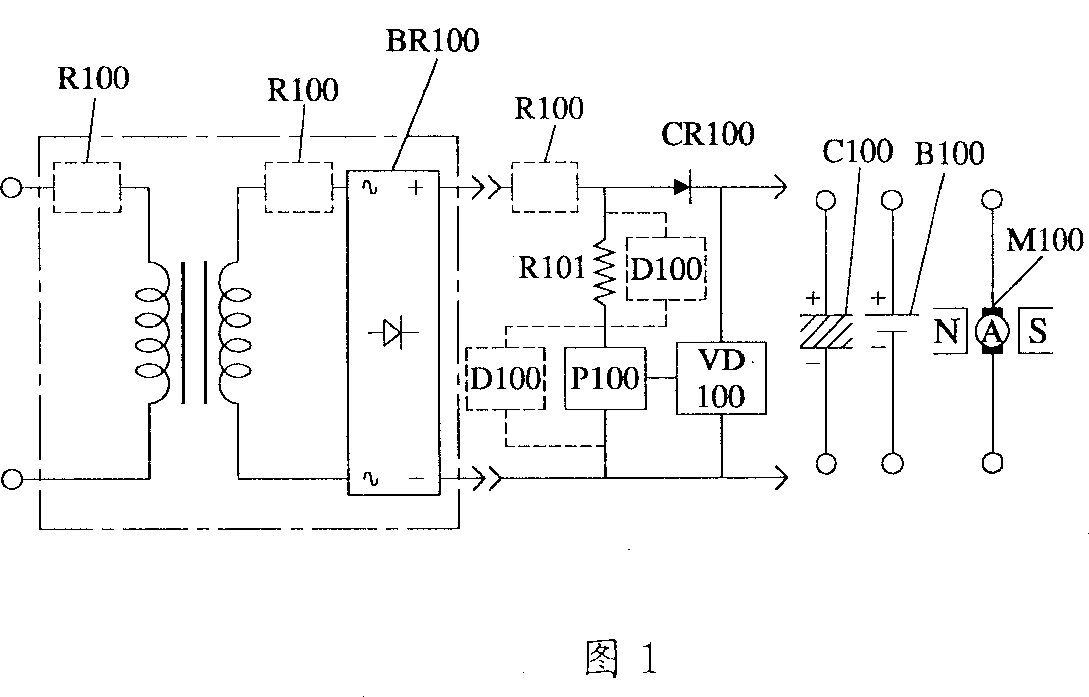
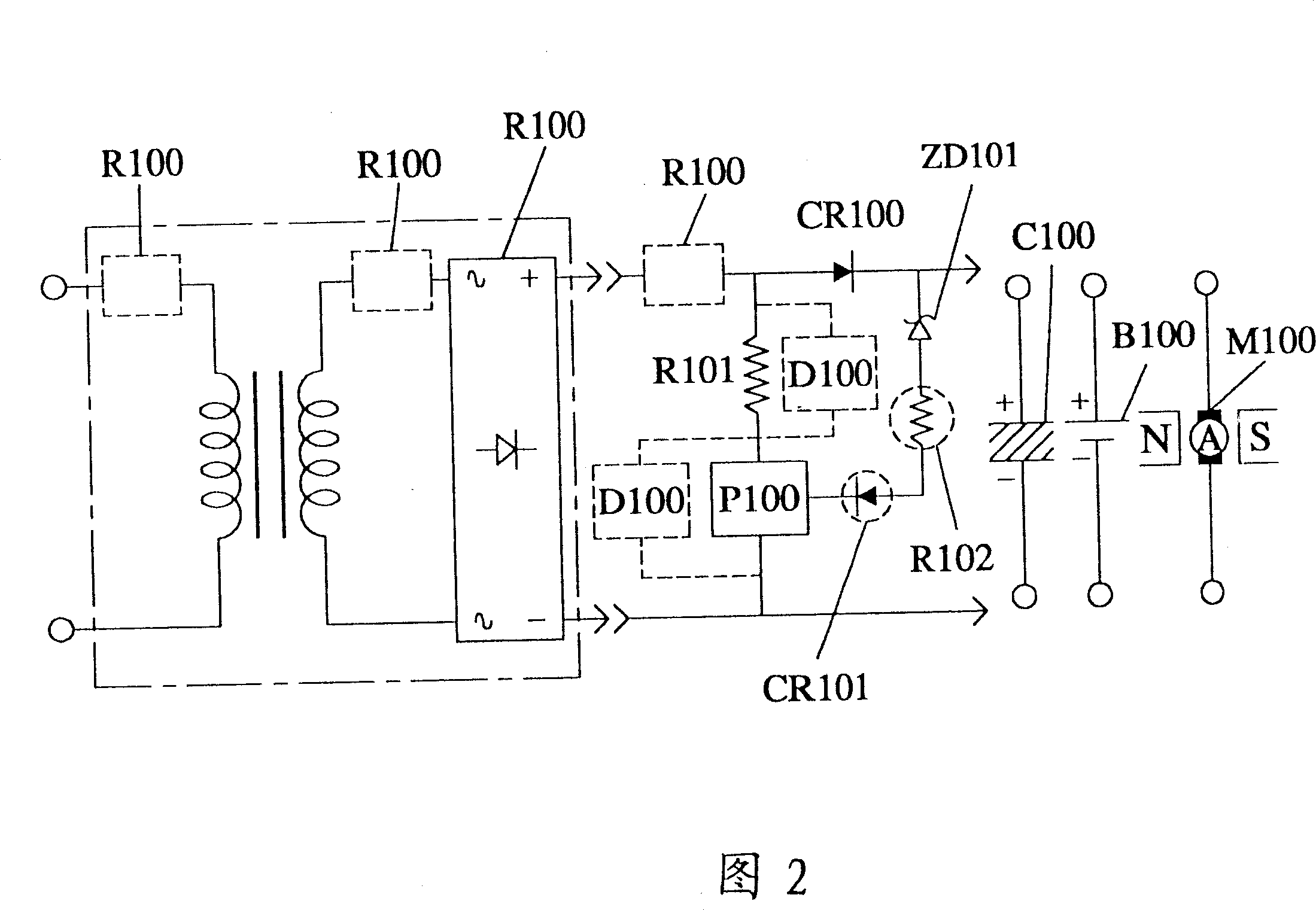
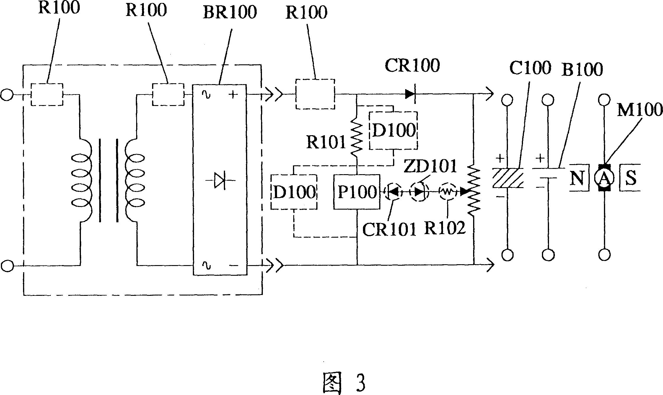
[0009] The present invention will be described in detail below with reference to the accompanying drawings.

[0010] In the shunt type automatic regulation output circuit with storage voltage or with potential load of the present invention, an isolation diode is connected in series between a DC power supply and a battery load or a DC motor load with armature back EMF, and the voltage storage load is Or when the voltage at both ends of the load with back EMF rises to exceed the set value, a load voltage detection circuit controls a shunt resistor connected in parallel with the power supply side to shunt current through the shunt resistor, so that the voltage across the load drops.

[0011] The DC power supply is the DC power supply output after the AC mains is rectified by the rectifier or is directly an independent DC power supply; the shunt resistor is connected in series with a power control element and then connected in parallel to the output end of the power supply or after...


PUM


Abstract

The present invention relates to a shunt type automatic regulating and control output circuit with voltage-storing or counter-electromotive force load, and is characterized by that between D.C. power supply and storage cell load or D.C. motor load with armature-reaction magnetomotive force an isoaltion diode is series-connected, when the voltage of two ends of the above-mentioned load is raised, and exceeds set value, it utilizes load voltage detection circuit to control shunt resistor parallely-connected on the power supply side to make it conduct so as to reduce voltage of two ends of load and reduce electric energy inputted into load.

Description

technical field [0001] The present invention relates to a shunt type automatic regulation output circuit with stored voltage or with back EMF load. Background technique [0002] Traditional automatic control output circuits for driving batteries or capacitors or supercapacitors or DC motors with armature back EMF usually connect active control elements in series with the load to control the load voltage or current, but the cost is relatively high due to the complexity of the circuit. SUMMARY OF THE INVENTION [0003] The main purpose of the present invention is to provide a shunt type automatic regulation output circuit with a voltage storage or a back EMF load. [0004] In the shunt type automatic regulation output circuit with storage voltage or back-EMF load of the present invention, an isolation diode is serially connected in series between the DC power supply and the load formed by the battery load or the DC motor with armature back-EMF. When the voltage at both ends...

Claims


Application Information

Patent Timeline
Patent Type & Authority Patents(China)
IPC IPC(8): G05F1/46H02J7/04H01M10/44H02H9/04H02J1/00H02J7/00H02M7/12H02M7/217H02P7/28
CPCH02H9/04H02M7/217H02P7/281H02J7/00302H02J7/00308
Inventor 杨泰和
Owner 杨泰和
Why Eureka
Try Eureka