Construction and receiving method of superwide band pulse wave signal
An ultra-wideband pulse and waveform signal technology, applied in electrical components, transmission systems, etc., can solve the problems of high energy value of the basic pulse autocorrelation function and high system bit error rate, reduce carrier generation and frequency mixing and other links, simplify System structure, the effect of improving bit error characteristics
- Summary
- Abstract
- Description
- Claims
- Application Information
AI Technical Summary
Problems solved by technology
Method used
Image
Examples
specific Embodiment approach 1
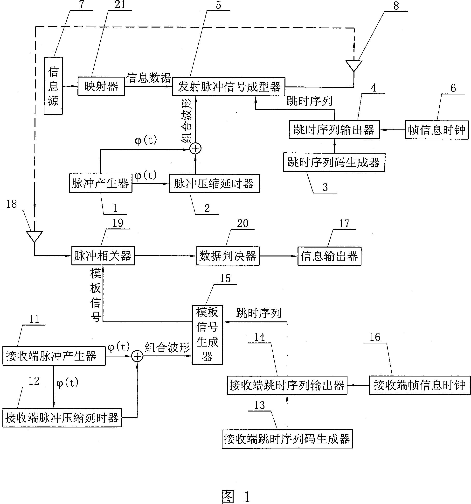
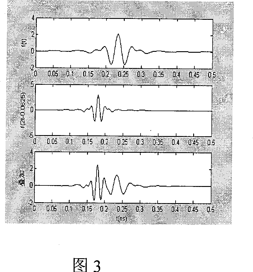
[0006] Specific Embodiment 1: The present embodiment will be specifically described below with reference to FIG. 1 . This embodiment is realized through the following steps: one, the pulse generator 1 sends the original pulse signal (t), and the pulse compression delayer 2 carries out the original pulse signal (t) respectively after i times of compression and time translation and compares with the original pulse signal (t) carries out weighted superposition, thereby forms a combined waveform; Simultaneously, the time-hopping sequence code generated by the time-hopping sequence code generator 3 and the clock signal produced by the frame information clock 6 are completed differently in the time-hopping sequence output device 4 The time delay of time delay, generate time-hopping sequence; Two, the information data that is input into the transmission pulse signal shaper 5 by information source 7 and combined waveform phase modulation, complete the informatization of combined wav...
specific Embodiment approach 2
[0007] Embodiment 2: The difference between this embodiment and Embodiment 1 is: it also includes a mapper 21, and the mapper 21 maps the binary data output by the information source 7 into "1" and "-1" and transmits them to the transmission pulse The signal shaper 5 and the data decision unit 20 are configured to judge a value greater than 0 output by the pulse correlator 19 as "1", and judge a value smaller than 0 as "-1". In this embodiment, the data decision unit 20 is a zero-crossing comparator. In this way, the multiplication of "1" or "-1" output by the mapper 21 with the combination waveform directly obtains the combination waveform of positive phase and the combination waveform of reverse phase, which is convenient for transmission and demodulation. Other composition and connection modes are the same as those in Embodiment 1. This embodiment is suitable for TH-BPSK system. As shown in Figure 1, in a system containing Nu users, the pulse generator 1 generates the ori...
specific Embodiment approach 3
[0021] Specific Embodiment Three: The present embodiment will be specifically described below with reference to FIG. 6 . The difference between this embodiment and Embodiment 1 is that it also includes binary and quaternary data converters 22, a delay device 23, a No. 1 inverter 24, a No. 2 inverter 25, and a receiving end delay device 26 , No. 3 inverter 27, No. 4 inverter 28, No. 0 correlator 30, No. 1 correlator 31, No. 2 correlator 32, No. 3 correlator 33 and four binary data converters 40, pulse generator 1 The original pulse signal (t) produced is an orthogonal wavelet signal, and the original pulse signal (t) is input to the delayer 23 and outputs a 0-delay signal (t), a primary delay signal (t-1) and two The secondary delay signal (t-2), the original pulse signal (t) is input to the pulse compression delayer 2 and then the output signal (2t), the second delay signal (t-2) and the signal (2t) After being superimposed, one combined waveform W0 is formed. The se...
PUM
 Abstract
Description
Claims
Application Information
 - R&D
- Intellectual Property
- Life Sciences
- Materials
- Tech Scout
- Unparalleled Data Quality
- Higher Quality Content
- 60% Fewer Hallucinations
Browse by: Latest US Patents, China's latest patents, Technical Efficacy Thesaurus, Application Domain, Technology Topic, Popular Technical Reports.
© 2025 PatSnap. All rights reserved.Legal|Privacy policy|Modern Slavery Act Transparency Statement|Sitemap|About US| Contact US: help@patsnap.com


